310AAV/JAV Induced-Combustion 4-Way Multipoise Furnace Installation, Start-up, Operating, and Service and Maintenance Instructions -Series C The 310AAV/JAV 4-Way Multipoise Gas Furnace was designed by Bryant dealers for Bryant dealers. Applications are easy with 4-way multipoise design, through-the-furnace downflow venting, 13 different venting options, and a door designed for easy service access. An inner blower door is provided for tighter sealing in sensitive applications.
Single-Stage Induced-Combustion 4-Way Multipoise Furnace Cancels: II 310A-45-4/IM-PG8J-04 II310A-45-5/IM-PG8J-05 Installation, Start-up, Operating, and Service and Maintenance Instructions Series 120/C NOTE: Read the entire instruction manual before starting the installation. This symbol → indicates a change since the last issue. → Portions of the text and tables are reprinted from NFPA 54/ANSI Z223.
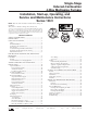
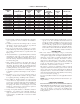
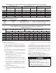
28-7/8" 26-1/8" (FLUE COLLAR) 25-1/4" 2-7/16" A 22-9/16" JUNCTION BOX LOCATION F 5-15/16" 1-5/16" D 19" 13/16" 13/16" 1-1/8" 4-13/16" 8-9/16" 7/8" DIA ACCESSORY AIRFLOW 1/2" DIA THERMOSTAT WIRE ENTRY OUTLET 1/2" DIA. K.O.THERMOSTAT WIRE ENTRY 1-3/4" DIA.RIGHT HAND GAS ENTRY 11/16" 7-3/4" 9-5/8" 11-1/2" 3-15/16" LEFT HAND GAS ENTRY 7/8" DIA. K.O. WIRE ENTRY 33-5/16" ALTERNATE JUNCTION BOX LOCATIONS (TYP) 24-7/8" VENT OUTLET 5 PLACES (TYP) 7/8" DIA. ACCESSORY 14-7/8" 7/8" DIA.
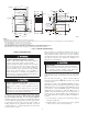
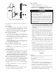
INSTALLATION TOP / PLENUM DESSUS / CHAMBRED'AIR MINIMUM INCHES CLEARANCE TO COMBUSTIBLE CONSTRUCTION DISTANCE MINIMALE EN POUCES AUX CONSTRUCTIONS COMBUSTIBLES This forced air furnace is equipped for use with This furnace is approved for UPFLOW, DOWNFLOW, and HORIZONTAL installations. natural gas at altitudes 0-10,000 ft (0-3,050m). Cette fournaise est approuvée pour l 'installation HORIZONTALE An accessory kit, supplied by the et la circulation d 'air VERS LE HAUT et VERS LE BAS.
→ Table 1—Dimensions (IN.) FURNACE SIZE A CABINET WIDTH D SUPPLY-AIR WIDTH (IN.) 045-08/024045 045-12/036045 070-08/024070 070-12/036070 070-16/048070 090-14/042090 090-16/048090 090-20/060090 110-12/036110 110-16/048110 110-22/066110 135-16/048135 135-22/066135 155-20/060155 14-3/16 14-3/16 14-3/16 14-3/16 17-1/2 17-1/2 21 21 17-1/2 21 21 21 24-1/2 24-1/2 12-9/16 12-9/16 12-9/16 12-9/16 15-7/8 15-7/8 19-3/8 19-3/8 15-7/8 19-3/8 19-3/8 19-3/8 22-7/8 22-7/8 E RETURN-AIR WIDTH (IN.
→ Step 8—Venting • US: NFGC; chapters 10 and 13 • CANADA: NSCNGPIC Part 7 and Appendix C ELECTROSTATIC DISCHARGE (ESD) PRECAUTIONS PROCEDURE → FURNACE RELIABILITY HAZARD Improper installation or service of furnace may cause premature furnace component failure. Electrostatic discharge can affect electronic components. Take precautions during furnace installation and servicing to protect the furnace electronic control.
THE BLOWER IS LOCATED BELOW THE BURNER SECTION, AND CONDITIONED AIR IS DISCHARGED UPWARD. THE BLOWER IS LOCATED TO THE RIGHT OF THE BURNER SECTION, AND AIR CONDITIONED AIR IS DISCHARGED TO THE LEFT. THE BLOWER IS LOCATED TO THE LEFT OF THE BURNER SECTION, AND CONDITIONED AIR IS DISCHARGED TO THE RIGHT. THE BLOWER IS LOCATED ABOVE THE BURNER SECTION, AND CONDITIONED AIR IS DISCHARGED DOWNWARD A02097 Fig.
→ → PERSONAL INJURY AND/OR PROPERTY DAMAGE HAZARD Improper use or installation of this furnace may cause premature furnace component failure. This gas furnace may be used for heating buildings under construction provided that: -The furnace is permanently installed with all electrical wiring, piping, venting and ducting installed according to these installation instructions. A return air duct is provided, sealed to the furnace casing, and terminated outside the space containing the furnace.
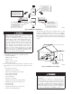
→ Table 2–Minimum Free Area Required for Each Combustion Air Opening or Duct to Outdoors TWO HORIZONTAL DUCTS SINGLE DUCT OR OPENING TWO OPENINGS OR VERTICAL DUCTS FURNACE (1 SQ. IN./2,000 BTUH) (1,100 SQ. MM/KW) (1 SQ. IN./3,000 BTUH) (734 SQ. MM/KW) (1 SQ. IN./4,000 BTUH) (550 SQ. MM/KW) INPUT Free Area of Free Area of Free Area of Round Duct Round Duct Round Duct (BTUH) Opening and Duct Opening and Duct Opening and Duct (in. Dia) (in. Dia) (In. Dia) (Sq. In.) (sq In.) (Sq In.) 44,000 22 6 14.
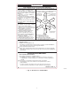
1 SQ IN. PER 4000 BTUH* 1 SQ IN. PER 2000 BTUH* 12″ MAX A VENT THROUGH ROOF CLEARANCE IN FRONT OF COMBUSTION AIR OPENINGS SHALL BE AT LEAST 3 IN. DUCTS TO OUTDOORS CIRCULATING AIR DUCTS 12″ MAX F 1 SQ IN. PER 4000 BTUH* OUTDOORS B D VENT THROUGH ROOF CLEARANCE IN FRONT OF COMBUSTION AIR OPENINGS SHALL BE AT LEAST 3 IN. 12″ MAX 1 SQ IN. PER 2000 BTUH* CIRCULATING AIR DUCTS DUCTS TO OUTDOORS INTERIOR HEATED SPACE 1 SQ IN. PER 4000 BTUH* E G 12″ MAX C 12" MAX 1 SQ IN.
c. Combining space on different floor levels. The volumes of spaces on different floor levels shall be considered as communicating spaces if connected by one or more permanent openings in doors or floors having free area of at least 2 in.2/1,000 Btuh (4,400 mm2/kW) of total input rating of all gas appliances. 2.
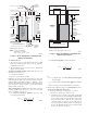
5⁄16″ Platform Furnace Support Construct working platform at location where all required furnace clearances are met. (See Fig. 2 and 17.) For furnaces with 1-in. clearance requirement on side, set furnace on non-combustible blocks, bricks or angle iron. For crawlspace installations, if the furnace is not suspended from the floor joists, the ground underneath furnace must be level and the furnace set on blocks or bricks.
Table 4—Opening Dimensions (In.
FURNACE (OR COIL CASING WHEN USED) A PLENUM OPENING B COMBUSTIBLE FLOORING D FLOOR OPENING DOWNFLOW SUBBASE C SHEET METAL PLENUM FLOOR OPENING A96283 Fig. 11—Floor and Plenum Opening Dimensions A96285 Fig. 12—Furnace, Plenum, and Subbase Installed on a Combustible Floor FURNACE CD5 OR CK5 COIL ASSEMBLY OR KCAKC COIL BOX COMBUSTIBLE FLOORING SHEET METAL PLENUM FLOOR OPENING A04140 → Fig.
DOWNFLOW UPFLOW HORIZONTAL 90˚ 90˚ PREFERRED 120˚ MIN PREFERRED PREFERRED PREFERRED 120˚ MIN PERMITTED PREFERRED 120˚ MIN PERMITTED PREFERRED PERMITTED A02329 Fig. 14—Duct Flanges /4" THREADED ROD 4 REQ. 1 OUTER DOOR ASSEMBLY SECURE ANGLE IRON TO BOTTOM OF FURNACE WITH 3 #8 x 3/4" SCREWS TYPICAL FOR 2 SUPPORTS 8" MIN FOR DOOR REMOVAL 1" SQUARE, 11/4" x 11/4" x 1/8" ANGLE IRON OR UNI-STRUT MAY BE USED (2) HEX NUTS, (2) WASHERS & (2) LOCK WASHERS REQ. PER ROD A05027 → Fig.
A02014 Fig. 16—Horizontal Suspension with Straps LINE CONTACT ONLY PERMISSIBLE BETWEEN LINES FORMED BY INTERSECTIONS OF THE TOP AND TWO SIDES OF THE FURNACE JACKET AND BUILDING JOISTS, STUDS, OR FRAMING. 17 3/4″ OVER ALL 4 3/4″ UNDER DOOR 1″ UNDER FURNACE GAS ENTRY TYPE-B VENT IN* 6″ M EXTEND OUT 12″ OUT FROM FACE OF DOOR 30-IN. MIN WORK AREA * WHEN USED WITH SINGLE WALL VENT CONNECTIONS 17 3/4″ SHEET METAL 22″ MANUAL SHUTOFF GAS VALVE SEDIMENT TRAP A02164 Fig.
→ Table 5—Air Delivery - CFM (With Filter)* FURNACE SIZE 024045 036045 024070 036070 048070 042090 048090 RETURN-AIR INLET Bottom or Side(s) Bottom or Side(s) Bottom or Side(s) Bottom or Side(s) Bottom or Side(s) Bottom or Side(s) Bottom or Side(s) Bottom Only 060090 Both Sides or 1 Side & Bottom 1 Side Only 036110 048110 Bottom or Side(s) Bottom or Side(s) Bottom Only 066110 Bottom Sides or 1 Side & Bottom 1 Side Only SPEED High Med-High Med-Low High Med-High Med-Low High Med-High Med-Low H
→ Table 5—Air Delivery - CFM (With Filter)* (Continued) FURNACE SIZE RETURN-AIR INLET 048135 Bottom or Side(s) Bottom Only 066135 Bottom, Sides or 1 Side & Bottom 1 Side Only Bottom Only 060155 Both Sides Or 1 Side & Bottom 1 Side Only SPEED High Med-High Med-Low High Med-High Med-Low High Med-High Med-Low High Med-High Med-Low High Med-High Med-Low High Med-High Med-Low High Med-High Med-Low 0.1 2090 1790 1545 2485 2195 1880 -2180 1880 -2135 1880 2465 2115 1800 -2155 1800 -2140 1800 0.
Fig. 18—Upflow Return Air Configurations and Restrictions Fig. 19—Downflow Return Air Configurations and Restrictions A02075 A02163 A02162 Fig.
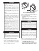
→ Table 6—Maximum Capacity of Pipe* NOMINAL IRON PIPE SIZE (IN.) 1/2 3/4 1 1-1/4 1-1/2 ELECTRICAL SHOCK AND FIRE HAZARD Failure to follow this warning could result in serious injury, death, or property damage. The cabinet MUST have an uninterrupted or unbroken ground according to NEC ANSI/NFPA 70-2002 and Canadian Electrical Code CSA C22.1 or local codes to minimize personal injury if an electrical fault should occur.
→ Table 7—Electrical Data FURNACE SIZE VOLTSHERTZPHASE 045-08/024045 045-12/036045 070-08/024070 070-12/036070 070-16/048070 090-14/042090 090-16/048090 090-20/060090 110-12/036110 110-16/048110 110-22/066110 135-16/048135 135-22/066135 155-20/060155 115-60-1 115-60-1 115-60-1 115-60-1 115-60-1 115-60-1 115-60-1 115-60-1 115-60-1 115-60-1 115-60-1 115-60-1 115-60-1 115-60-1 OPERATING MAXIMUM MAXIMUM UNIT MAXIMUM MINIMUM VOLTAGE RANGE FUSE OR CKT BKR UNIT AMPS AMPACITY# WIRE LENGTH (FT)‡ WIRE GAUGE AMPS†
TWINNING AND/OR COMPONENT TEST TERMINAL BLOWER OFF-DELAY J2 JUMPER BLOWER OFF-DELAY 120 180 90 150 J2 HUMIDIFIER TERMINAL (24-VAC 0.5 AMP MAX.) G Com 24V 24-V THERMOSTAT TERMINALS W TRANSFORMER 24-VAC CONNECTIONS PLT Y TEST/TWIN R HUM 0.
FIELD 24-V WIRING FIELD 115-, 208/230-, 460-V WIRING FACTORY 24-V WIRING FACTORY 115-V WIRING NOTE 2 W FIVE WIRE THREE-WIRE HEATING-ONLY C R G Y THERMOSTAT TERMINALS FIELD-SUPPLIED DISCONNECT 208/230- OR 460-V THREE PHASE BLOWER DOOR SWITCH BLK W BLK WHT WHT GND 115-V FIELDSUPPLIED DISCONNECT GND AUXILIARY J-BOX C O N T R O L R 208/230-V SINGLE PHASE G COM GND NOTE 1 CONDENSING UNIT Y/Y2 24-V TERMINAL BLOCK FURNACE TWO WIRE NOTES: 1.
The following information and warning must be considered in addition to the requirements defined in the NFGC and the NSCNGPIC. CARBON MONOXIDE POISONING HAZARD Failure to follow the steps outlined below for each appliance connected to the venting system being placed into operation could result in carbon monoxide poisoning or death.
4. The input rating of each space heating appliance is greater than the minimum input rating given in Table B for the local 99% Winter Design Temperature. Chimneys having internal areas greater than 38 square inches require furnace input ratings greater than the input ratings of these furnaces. See footnote at bottom of Table B, and Table B—Minimum Alowable Input Rating of Space-Heating Appliance in Thousands of BTU per Hour VENT HEIGHT (FT) 5. The authority having jurisdiction approves.
CHIMNEY INSPECTION CHART For additional requirements refer to the National Fuel Gas Code NFPA 54/ANSI Z223.1 and ANSI/NFPA 211 Chimneys, Fireplaces, Vents, and Solid Fuel Burning Appliances in the U.S.A. or to the Canadian installation Code CSA-B149.1 in Canada. Crown condition: Missing mortar or brick? Rebuild crown. Yes No Is chimney property lined with clay tile liner? No Yes Is liner and top seal in good condition? No Repair liner or top seal or reline chimney as necessary.
4. Set the thermostat heat anticipator or cycle rate to reduce short cycling. Air for combustion must not be contaminated by halogen compounds which include chlorides, fluorides, bromides, and iodides. These compounds are found in many common home products such as detergent, paint, glue, aerosol spray, bleach, cleaning solvent, salt, and air freshener, and can cause corrosion of furnaces and vents. Avoid using such products in the combustion-air supply.
A04131 → Fig. 31—Remove Knockout with Hammer START-UP, ADJUSTMENT, AND SAFETY CHECK Step 1—General A04128 → Fig. 28—Rounded End of Knockout FIRE HAZARD Failure to follow this warning could result in a fire and lead to property damage, personal injury, or death. This furnace is equipped with manual reset limit switches in the gas control area. The switches open and shut off power to the gas valve if a flame rollout or overheating condition occurs in the gas control area. DO NOT bypass the switches.
SEE NOTES: 1,2,4,7,8,9 on the page following these figures SEE NOTES: 1,2,4,5,7,8,9 on the page following these figures A03208 A03211 Fig. 32—Upflow Application-Vent Elbow Up Fig. 35—Downflow Application-Vent Elbow Up SEE NOTES: 1,2,4,5,6,7,8,9,10 on the page following these figures SEE NOTES: 1,2,3,4,7,8,9 on the pages following these figures Fig. 36—Downflow ApplicationVent Elbow Left then Up A03209 A03207 Fig.
SEE NOTES: 1,2,4,7,8,9 on the page following these figures SEE NOTES: 1,2,4,5,7,8,9 on the page following these figures A03213 Fig. 38—Horizontal Left Application-Vent Elbow Left A03215 Fig. 40—Horizontal Left Application-Vent Elbow Up SEE NOTES: 1,2,4,5,7,8,9 on the page following these figures SEE NOTES: 1,2,4,5,7,8,9 on the page following these figures A03214 Fig. 41—Horizontal Left Application-Vent Elbow Right Fig.
SEE NOTES: 1,2,4,5,7,8,9 A02068 Fig. 44—Horizontal Right Application-Vent Elbow Left Venting Notes for Figures 32-44 1. For common vent, vent connector sizing and vent material: United States--use the NFGC Canada--use the NSCNGPIC 2. Immediately increase to 5-inch or 6-inch vent connector outside furnace casing when 5-inch vent connector is required, refer to Note 1 above. 3.
1. Determine the correct gas input rate. In the U.S.A.: The input rating for altitudes above 2,000 ft. must be reduced by 4 percent for each 1,000 ft. above sea level. For installations below 2000 ft., refer to the unit rating plate. For installations above 2000 ft., multiply the input on the rating plate by the de-rate multiplier in Table 8 for the correct input rate. In Canada: The input rating must be derated by 10 percent for altitudes of 2,000 ft. to 4,500 ft.
32 L E G E N D GND GV GVR HSI HSIR HUM IDM IDR ILK J1 J2 JB LED LGPS START BLWM EAC-1 BLU PL1 RED BRN 2 YEL ORN CAP GRN/YEL PR1 PL2 WHT BRN RED PCB GRN/YEL 1 WHT BLK BLK WHT ILK BLK NOTE #11 LS2 RED WHT BLK ORG GRN/YEL IDM (WHEN USED) ORG BVSS NOTE #10 (WHEN USED) RED DSS LS1 IDR CPU 24VAC SEC-2 2 1 BHT/CLR GVR COOL HEAT SPARE-1 2 1 PL1-5 PL1-10 PL1-4 PL1-2 PL1-8 PL1-6 PL3 LS1 PLUG RECEPTACLE FIELD SPLICE EQUIPMENT GROUND FIELD EARTH GROUND
REGULATOR SEAL CAP Table 8–Altitude Derate Multipler for U.S.A. ALTITUDE (FT) 0–2000 2001–3000 3001–4000 4001–5000 5001–6000 6001–7000 7001–8000 8001–9000 9001–10,000 PERCENT OF DERATE 0 8–12 12–16 16–20 20–24 24–28 28–32 32–36 36–40 DERATE MULTIPLIER FACTOR* 1.00 0.90 0.86 0.82 0.78 0.74 0.70 0.66 0.
THERMOSTAT SUBBASE TERMINALS WITH THERMOSTAT REMOVED (ANITICIPATOR, CLOCK, ETC., MUST BE OUT OF CIRCUIT.) Table 9—Speed Selection COLOR SPEED White Common AS SHIPPED BLW Black High COOL Yellow† Med-High SPARE Blue* Med-Low SPARE Red* Low HEAT HOOK-AROUND AMMETER * 1/5 HP motor models: BLUE to HEAT, RED to SPARE. † Not available on 1/5 HP motors. NOTE: Continuous blower is the HEAT speed. R Y W G d. Turn thermostat down below room temperature and remove blower access door. e.
status code 32. If hot surface igniter glows when inducer motor is disconnected, shut down furnace immediately. Table 10–GAS RATE (CU FT/HR) SIZE OF TEST DIAL SIZE OF TEST DIAL SECONDS SECONDS FOR 1 FOR 1 1 2 5 1 2 5 REVOLUTION Cu Ft Cu Ft Cu Ft REVOLUTION Cu Ft Cu Ft Cu Ft → e. Determine reason pressure switch did not function properly and correct condition. 10 360 720 1800 50 72 144 360 f. Turn off 115-v power to furnace.
SERVICE If status code recall is needed, briefly remove then reconnect one main limit wire to display stored status code. On RED LED boards do not remove power or blower door before initiating status code recall. After status code recall is completed component test will occur. LED CODE STATUS CONTINUOUS OFF - Check for 115VAC at L1 and L2, and 24VAC at SEC-1 and SEC-2. CONTINUOUS ON - Control has 24VAC power. RAPID FLASHING - Line voltage (115VAC) polarity reversed.
4. Inspect burner compartment before each heating season for rust, corrosion, soot or excessive dust. If necessary, have furnace and burner serviced by a qualified service agency. Table 11—FILTER SIZE INFORMATION (IN.) FURNACE CASING WIDTH 14-1/2 17-1/2 21 24** FILTER QUANTITY AND SIZE Side Return Bottom Return (1) 16 X 25 X 1 (1) 14 X 25 X 1 (1) 16 X 25 X 1 (1) 16 X 25 X 1 (1) 16 X 25 X 1 (1) 20 X 25 X 1 (1) 16 X 25 X 1 (1) 24 X 25 X 1 FILTER TYPE 5.
TABLE 12—Orifice Size* and Manifold Pressure For Gas Input Rate (Tabulated Data Based On 22,000 Btuh Per Burner, Derated 4 Percent For Each 1000 Ft Above Sea Level) U.S.A. and Canada ALTITUDE RANGE (FT) AVG GAS HEAT VALUE (BTU/CU FT) 0 to 2000 U.S.A. and Canada ALTITUDE RANGE (FT) AVG GAS HEAT VALUE (BTU/CU FT) U.S.A. Altitudes 2001 to 3000 or Canada Altitudes 2000 to 4500 ALTITUDE RANGE (FT) U.S.A.
Table 12—Orifice Size* And Manifold Pressure For Gas Input Rate (Continued) (Tabulated Data Based On 22,000 Btuh Per Burner, Derated 4 Percent For Each 1000 Ft Above Sea Level) U.S.A. Only ALTITUDE RANGE (FT) 5001 to 6000 U.S.A. Only ALTITUDE RANGE (FT) 6001 to 7000 U.S.A. Only ALTITUDE RANGE (FT) 7001 to 8000 U.S.A. Only ALTITUDE RANGE (FT) 8001 to 9000 AVG GAS HEAT VALUE AT ALTITUDE (BTU/CU FT) 0.58 Orifice Manifold No.
Table 12—Orifice Size* And Manifold Pressure For Gas Input Rate (Continued) (Tabulated Data Based On 22,000 Btuh Per Burner, Derated 4 Percent For Each 1000 Ft Above Sea Level) U.S.A. Only ALTITUDE RANGE (FT) 9001 to 10,000 AVG GAS HEAT VALUE AT ALTITUDE (BTU/CU FT) 0.58 Orifice Manifold No. Pressure 600 625 650 675 700 725 43 43 43 43 48 48 2.7 2.5 2.3 2.1 3.7 3.5 SPECIFIC GRAVITY OF NATURAL GAS 0.60 0.62 Orifice Manifold Orifice Manifold No. Pressure No. Pressure 43 43 43 43 43 48 2.8 2.6 2.4 2.
TABLE 13—Orifice Size* and Manifold Pressure For Gas Input Rate (Tabulated Data Based On 21,000 Btuh Per Burner, Derated 4 Percent For Each 1000 Ft Above Sea Level) U.S.A. and Canada ALTITUDE RANGE (FT) AVG GAS HEAT VALUE (BTU/CU FT) 0 to 2000 U.S.A. and Canada ALTITUDE RANGE (FT) AVG GAS HEAT VALUE (BTU/CU FT) U.S.A. Altitudes 2001 to 3000 or Canada Altitudes 2000 to 4500 ALTITUDE RANGE (FT) U.S.A.
Table 13—Orifice Size* And Manifold Pressure For Gas Input Rate (Continued) (Tabulated Data Based On 21,000 Btuh Per Burner, Derated 4 Percent For Each 1000 Ft Above Sea Level) U.S.A. Only ALTITUDE RANGE (FT) U.S.A. Only U.S.A. Only 43 43 43 43 43 43 43 43 AVG GAS HEAT VALUE AT ALTITUDE (BTU/CU FT) Orifice No. 675 700 725 750 775 800 825 850 43 43 43 43 43 43 43 48 AVG GAS HEAT VALUE AT ALTITUDE (BTU/CU FT) Orifice No.
Table 13—Orifice Size* And Manifold Pressure For Gas Input Rate (Continued) (Tabulated Data Based On 21,000 Btuh Per Burner, Derated 4 Percent For Each 1000 Ft Above Sea Level) U.S.A. Only ALTITUDE RANGE (FT) 9001 to 10,000 AVG GAS HEAT VALUE AT ALTITUDE (BTU/CU FT) 600 625 650 675 700 725 0.58 Orifice Manifold No. Pressure 43 43 43 48 48 49 2.4 2.3 2.1 3.6 3.4 3.7 SPECIFIC GRAVITY OF NATURAL GAS 0.60 0.62 Orifice Manifold Orifice Manifold No. Pressure No. Pressure 43 43 43 48 48 49 2.5 2.3 2.2 3.
b. Igniter Warm-Up- At the end of the prepurge period, the Hot-Surface Igniter HSI is energized for a 17-second igniter warm-up period. → c. Trial-for-Ignition Sequence- When the igniter warm-up period is completed the main gas valve relay contacts GVR close to energize the gas valve GV, the gas valve opens. The gas valve GV permits gas flow to the burners where it is ignited by the HSI. Five seconds after the GVR closes, a 2-second flame proving period begins.
the blower switches to COOL speed after a 3 second delay. If the R-to-W-and-Y-and-G signals disappear at the same time, the blower motor BLWM will remain on for the selected blower-OFF delay period. If the R-to-W-and-Y signals disappear, leaving the G signal, the blower motor BLWM will continue running the blower motor BLWM at HEAT speed after the selected blower-OFF delay period is completed. period at HEAT speed. When the thermostat ″calls for cooling″, the blower motor BLWM will operate at COOL speed.
46 Go to section below for the status code that was flashed. Determine status code. The status code is a 2 digit number with the first digit determined by the number of short flashes and the second digit by the number of long flashes? YES Is LED status light blinking ON/OFF slowly with a combination of short and long flashes? NO Is LED status light blinking rapidly without a pause? YES START Is LED status light on? YES NO YES NO NO YES Replace furnace control.
47 24 SECONDARY VOLTAGE FUSE IS OPEN Check for: - Short circuit in secondary voltage (24V) wiring including thermostat leads. Disconnect thermostat leads to isolate short circuit. 23 PRESSURE SWITCH DID NOT OPEN Check for: - Obstructed pressure tube. - Pressure switch stuck closed. 22 ABNORMAL FLAME-PROVING SIGNAL Flame is proved while gas valve is deenergized. Inducer will run until fault is cleared. Check for: - Stuck open or leaky gas valve.
Copyright 2005 Carrier Corporation 58st13si Manufacturer reserves the right to discontinue, or change at any time, specifications or designs without notice and without incurring obligations. Book 1 4 PC 101 Catalog No. See Cover Printed in U.S.A.