
Instruction manual

2. Remove outer door and blower access door.
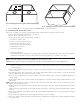
3. For upflow and downflow applications:
a. For upflow applications:
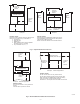
Bottom return air usage is required as part of any upflow return air configuration. If additional return air is to enter 1 side of each
furnace, in addition to bottom return air, cut open 1 entire return-air opening in appropriate side of each furnace. (See Fig. 1.)
WARNING: UNIT DAMAGE AND FIRE HAZARD
Failure to follow this warning could cause fire, personal injury, or death.
DO NOT use the back of the furnace for return-air duct connections in upflow position, as limit cycling will occur.
b. For downflow applications:
Return air can only be connected to bottom opening of furnace. A common return air plenum is required for proper auxiliary limit switch
operation. (See Fig. 2.)
WARNING: UNIT DAMAGE AND FIRE HAZARD
Failure to follow this warning could result in unit damage, fire, personal injury or death.
DO NOT use the back or sides of the furnace for return-air duct connections in the downflow position, as limit switch cycling will occur.
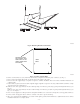
4. Remove bottom closure panels from both furnaces. (See Fig. 4.)
a. Lay furnaces on back or sides.
b. Remove 2 screws from bottom front panel.
c. Rotate front panel downward to remove.
d. Remove bottom closure panel and discard.
e. Reinstall bottom front panel.
f. Stand furnaces upright.
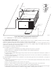
5. Apply 2 factory-supplied foam strips to mating side of each furnace. Locate strips equal distance from top and bottom as shown in Fig. 5.
Trim off excess material.
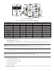
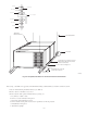
Fig. 3—Dimensional Drawing
A02235
A
D
E
A
D
E
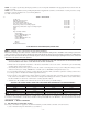
Table 2—Dimensions (IN.) for Two-Stage with PSC Blower
UNIT SIZE A B C VENT CONN.* SHIP WT. (LB)
045-08/024045 14–3/16 12–9/16 12–11/16 4 116
045-120/036045 14–3/16 12–9/16 12–11/16 4 117
070-08/024070 14–3/16 12–9/16 12–11/16 4 120
070-12/036070 14–3/16 12–9/16 12–11/16 4 126
070-16/048070 17–1/2 15–7/8 16 4 135
090-14/042090 17–1/2 15–7/8 16 4 137
090-16/048090 21 19–3/8 19–1/2 4 150
090-20/060090 21 19–3/8 19–1/2 4 155
110-12/036110 17–1/2 15–7/8 16 4 145
110-16/048110 21 19–3/8 19–1/2 4 157
110-22/066110 21 19–3/8 19–1/2 4 162
135-16/048135 21 19–3/8 19–1/2 4 162
135-22/066135 24–1/2 22–7/8 23 4 174
155-20/060155 24–1/2 22–7/8 23 4 181
5” or 6” vent connector may be required in some cases
—5—