
Instruction manual
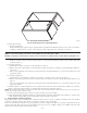
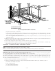

6. For downflow applications:
a. Position furnaces on downflow kits (no A/C coils) or on entering air-side of A/C coils. Adjust and shim each furnace to align unused
condensate drain line holes in lower section of both furnaces holes, which will be used for wire routing between furnaces. (Similar to
Fig. 29.)
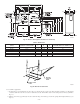
b. Drill two 1/8-in. holes, approximately 1 in. below return air flange, from inside top of return air opening and through both furnaces. (See
Fig. 25.)
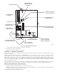
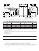
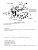
Fig. 21—Back-to-Back (Upflow, Downflow or Horizontal)
A02234
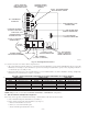
Table 4—Dimensions
INPUT HEATING SIZE
(BTUH)
NOMINAL COOLING SIZE A D E TWINNED FURNACE WEIGHT (LBS)
60,000 48,000 17–1/2 15-7/8 16 350
80,000* 48,000 17–1/2 15-7/8 16 410
80,000 60,000 21 19-3/8 19-1/2 228
100,000* 48,000 21 19-3/8 19-1/2 458
100,000* 60,000 21 19-3/8 19-1/2 464
120,000* 60,000 24–1/2 22–7/8 23 522
* Two Speed Furnace Capacities and Dimensions
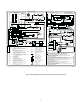
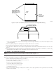
Fig. 22—Bottom Closure Panel
A93047
BOTTOM
CLOSURE
PANEL
FRONT FILLER
PANEL
—26—