
Furnace User Manual

32
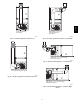
SEE NOTES: 1,2,4,7,8,9 on the page
following these figures
A03218
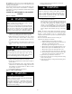
Fig. 44 -- Horizo ntal Right Application -- Vent Elbow Right
SEE NOTES: 1,2,4,5,7,8,9 on the page
following these figures
A03215
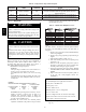
Fig. 45 -- Horizontal Left Application -- Vent Elbow Up
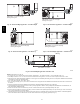
SEE NOTES: 1,2,4,5,7,8,9 on the page
following these figures
A03216
Fig. 46 -- Horizontal Left Application -- Vent Elbow Right
SEE NOTES: 1,2,4,5,7,8,9 on the page
following these figures
A03219
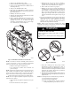
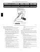
Fig. 47 -- Horizontal Right Application -- Vent Elbow Left
then Up
SEE NOTES: 1,2,4,5,7,8,9
A02068
Fig. 48 -- Horizontal Right Application--Vent Elbow Left
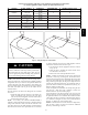
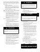
NOTES: Venting Notes for Fig. 36 ---48
1. For common vent, vent connector sizing a nd vent material: United States--- ---use the NFGC Canada--- ---use the CAN/CSA---B149.1 ---05
2. Immediately increase to 5---inch or 6 ---inch vent connector outside furnace casing when 5---inch vent connector is required, refer to Note 1 above.
3. Side outlet vent for u pfl ow and downflow installations must use Type B vent immediately after exiting the furna ce, except when K GAVG0101DFG, Downflow
VentGuardKit,isusedinthedownflowposition.
4. Type ---B vent where required, refer to Note 1 above.
5. Four---inch single---wal l (26 ga. min.) vent must be used inside furnace casing and when the K GAVG0101DFG Downflow Vent Guard Kit is used external to
the furnace.
6. Accessory D o wn f low Vent Guard Kit, KGAVG0101DFG required in downflow installations with lower vent con f iguration.
7. Chimney Adapter Kit may be r equ ired for exterior masonry chimney applications. Refer to Chimney Adapter Kit, KGACA02014FC or KGACA02015FC, fo r
sizing and complete application details.
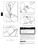
8. Secure vent connector to furnace elbow with (2) corrosion ---resistant sheet metal screws, spaced approximately 180_ apart.
9. Secure all other si ngle wall vent connector joints with (3) corrosion resistant screws spaced approximately 120_ apart. Secure Type---B vent connectors per
vent connector manufacturer’s recommendations.
10. The total height of the vent a nd connector shal l be at least seven feet for the 154,000 Btuh gas input rate model when installed in a downflow application
with furnace elbow turned to left side with the connector elbow outside furnace casing pointing upward. (See Fig. 41.)
312A