312A 2---Stage Deluxe Induced---Combustion 4---Way Multipoise Furnace Installation, Start--up, Operating and Service and Maintenance Instructions Series 120/C SAFETY CONSIDERATIONS . . . . . . . . . . . . . . . . . . . . . . . . 2 INTRODUCTION . . . . . . . . . . . . . . . . . . . . . . . . . . . . . . . . . . 3 CODES AND STANDARDS . . . . . . . . . . . . . . . . . . . . . . . . . . 5 ama Safety . . . . . . . . . . . . . . . . . . . . . . . . . . . . . . . . . . . . . . . . . . . 5 General Installation .
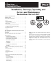
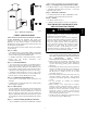
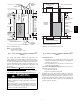
6-1/8" (FLUE COLLAR) 28-7/8" 25-1/4" 2-7/16" A 22-9/16" JUNCTION BOX LOCATION F 5-15/16" D AIRFLOW 1-5/16" 19" 13/16" OUTLET 1/2" DIA. K.O.THERMOSTAT WIRE ENTRY 1-3/4" DIA.RIGHT HAND GAS ENTRY 8-9/16" 7/8" DIA ACCESSORY 13/16" 1-1/8" 4-13/16" 1/2" DIA THERMOSTAT WIRE ENTRY 11/16" 7-3/4" 9-5/8" 11-1/2" 3-15/16" LEFT HAND GAS ENTRY 7/8" DIA. K.O. WIRE ENTRY 33-5/16" ALTERNATE JUNCTION BOX LOCATIONS (TYP) 24-7/8" VENT OUTLET 5 PLACES (TYP) 14-7/8" 7/8" DIA. ACCESSORY 7/8" DIA.
FURNACE SIZE 045--- 08/024045 045--- 12/036045 070--- 08/024070 070--- 12/036070 070--- 16/048070 090--- 14/042090 090--- 16/048090 090--- 20/060090 110--- 12/036110 110--- 16/048110 110--- 22/066110 135--- 16/048135 135--- 22/066135 155--- 20/060155 A CABINET WIDTH (IN.) 14--- 3/16 14--- 3/16 14--- 3/16 14--- 3/16 17--- 1/2 17--- 1/2 21 21 17--- 1/2 21 21 21 24--- 1/2 24--- 1/2 D SUPPLY ---AIR WIDTH (IN.) E RETURN---AIR WIDTH (IN.
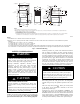
INSTALLATION O F R AN T AV DE SI É ÔT C * 0" FR A V ON T A NT SE EN R V I TR ET C E IE N 3"MIN BOTTOM DESSOUS Cette fournaise à air pulsé est équipée pour utilisation avec gaz naturel et altitudes comprises entre 0-3,050m (0-10,000 pi). Utiliser une trousse de conversion, fournie par le fabricant, pour passer au gaz propane ou pour certaines installations au gaz naturel. Cette fournaise est prévue pour être installée dans un bâtiment construit sur place.
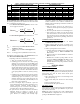
90B as tested by UL Standard 181 for Class I Rigid Air Ducts Step 6 — Gas Piping and Gas Pipe Pressure Testing 80 S US: NFGC; chapters 5, 6, and 7 and National Plumbing Codes S CANADA: CAN/CSA--B149.1--05 Parts 4, 5, 6 and 9 and Appendices A, B, E and H. Step 7 — Electrical Connections S US: National Electrical Code (NEC) ANSI/NFPA 70--2006 S CANADA: Canadian Electrical Code CSA C22.1 Step 8 — Venting S US: NFGC; chapters 12 and 13 S CANADA: CAN/CSA--B149.
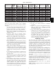
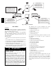
THE BLOWER IS LOCATED BELOW THE BURNER SECTION, AND CONDITIONED AIR IS DISCHARGED UPWARD. 312A THE BLOWER IS LOCATED TO THE RIGHT OF THE BURNER SECTION, AND AIR CONDITIONED AIR IS DISCHARGED TO THE LEFT. THE BLOWER IS LOCATED TO THE LEFT OF THE BURNER SECTION, AND CONDITIONED AIR IS DISCHARGED TO THE RIGHT. THE BLOWER IS LOCATED ABOVE THE BURNER SECTION, AND CONDITIONED AIR IS DISCHARGED DOWNWARD A02097 Fig.
WARNING ! FIRE, INJURY OR DEATH HAZARD Failure to follow this warning could result in personal injury, death, and/or property damage. When the furnace is installed in a residential garage, the burners and ignition sources must be located at least 18 inches above the floor. The furnace must be located or protected to avoid damage by vehicles.
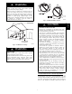
The requirements for combustion and ventilation air depend upon whether or not the furnace is located in a space having a volume of at least 50 cubic feet per 1,000 Btuh input rating for all gas appliances installed in the space. S Spaces having less than 50 cubic feet per 1,000 Btuh require the Outdoor Combustion Air Method. S Spaces having at least 50 cubic feet per 1,000 Btuh may use the Indoor Combustion Air, Standard or Known Air Infiltration Method. Outdoor Combustion Air Method 1.
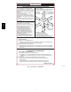
1 SQ IN. PER 2000 BTUH* 12″ MAX A F 1 SQ IN. PER 4000 BTUH* INTERIOR HEATED SPACE 1 SQ IN. PER 4000 BTUH* E G 12″ MAX C VENT THROUGH ROOF 1 SQ IN. PER 1000 BTUH* IN DOOR OR WALL UNCONFINED SPACE 6" MIN (FRONT)† 1 SQ IN. PER 1000 BTUH* IN DOOR OR WALL 12" MAX 12″ MAX CIRCULATING AIR DUCTS 12" MAX CIRCULATING AIR DUCTS DUCT TO OUTDOORS 1 SQ IN. PER 4000 BTUH* * Minimum opening size is 100 sq in. with minimum dimensions of 3 in. † Minimum of 3 in. . when type-B1 vent is used.
Table 3 – Minimum Space Volumes for 100% Combustion, Ventilation, and Dilution from Indoors ACH 0.60 0.50 0.40 0.30 0.20 0.10 0.
Leveling Legs (If Desired) In upflow position with side return inlet(s), leveling legs may be used. (See Fig. 10.) Install field--supplied, 5/16 X 1--1/2 in. (max) corrosion--resistant machine bolts, washers and nuts. NOTE: Bottom closure must be used when leveling legs are used. It may be necessary to remove and reinstall bottom closure panel to install leveling legs. To remove bottom closure panel, see item 1 in Bottom Return Air Inlet section in Step 1 above. To install leveling legs: 1.
312A underneath furnace must be level and the furnace set on blocks or bricks. Roll--Out Protection Provide a minimum 17--3/4 in. X 22 in. piece of sheet metal for flame roll--out protection in front of burner area for furnaces closer than 12 inches above the combustible deck or suspended furnaces closer than 12 inches to joists. The sheet metal MUST extend underneath the furnace casing by 1 in. with the door removed. The bottom closure panel on furnaces of widths 17--1/2 in.
Table 4 – Opening dimensions (In.
/4" THREADED ROD 4 REQ. 1 312A OUTER DOOR ASSEMBLY SECURE ANGLE IRON TO BOTTOM OF FURNACE WITH 3 #8 x 3/4" SCREWS TYPICAL FOR 2 SUPPORTS 8" MIN FOR DOOR REMOVAL 1" SQUARE, 11/4" x 11/4" x 1/4" ANGLE IRON OR UNI-STRUT MAY BE USED (2) HEX NUTS, (2) WASHERS & (2) LOCK WASHERS REQ. PER ROD A02345 Fig. 15 -- Horizontal Unit Suspension METHOD 2 USE (42) #8 x 3/4 SHEET METAL SCREWS TYPICAL FOR EACH STRAPS.THE STRAPS SHOULD BE VERTICAL AGAINST THE FURNACE SIDES AND NOT PULL AWAY FROM THE FURNACE SIDES.
LINE CONTACT ONLY PERMISSIBLE BETWEEN LINES FORMED BY INTERSECTIONS OF THE TOP AND TWO SIDES OF THE FURNACE JACKET AND BUILDING JOISTS, STUDS, OR FRAMING. 17 3/4″ OVER ALL 4 3/4″ UNDER DOOR 1″ UNDER FURNACE GAS ENTRY TYPE-B VENT IN* 6″ M EXTEND OUT 12″ OUT FROM FACE OF DOOR 30-IN. MIN WORK AREA * WHEN USED WITH SINGLE WALL VENT CONNECTIONS 17 3/4″ SHEET METAL 312A 22″ EQUIPMENT MANUAL SHUT-OFF GAS VALVE SEDIMENT TRAP UNION A03177 Fig.
Table 5 – Air Delivery -- CFM (With Filter)* 312A FURNACE SIZE RETURN---AIR INLET 045--- 08 / 024045 Bottom or Side(s) 045--- 12 / 036045 Bottom or Side(s) 070--- 081 / 024070 Bottom or Side(s) 070--- 12 / 036070 Bottom or Side(s) 070--- 16 / 048070 Bottom or Side(s) 090--- 14 / 042090 Bottom or Side(s) 090--- 16 / 048090 Bottom or Side(s) Bottom Only 090--- 20 / 060090 Both Side or 1 Side & Bottom 1Side Only 110--- 12 / 036110 Bottom or Side(s) 110--- 16 / 048110 Bottom or Side(s)
Bottom Only 110--- 22 / 066110 Bottom Sides or 1 Side & Bottom 1Side Only High Med --High Medium Med --- Low Low High Med --High High Med --High Medium Med --- Low Low 2530 2225 1895 1565 1320 2460 2190 1885 1555 1295 2380 2135 1865 1535 1265 2285 2075 1820 1505 1235 2200 1995 1770 1465 1205 2085 1910 1700 1410 1160 1970 1805 1610 1350 1105 1835 1695 1520 1265 1035 1695 1565 1410 1175 950 1545 1430 1290 1050 870 --- --2205 --- --2175 2415 2120 2330 2065 2235 1975 2125 1900 1995 1790 18
Table 5 -- Air Delivery -- CFM (With Filter)* (Cont.) FURNACE SIZE RETURN---AIR INLET Bottom or Side(s) 135--- 16 / 048135 Bottom Only Bottom Sides or 1 Side & Bottom 135--- 22 / 066135 312A 1 Side Only Bottom Only 155--- 20 / 060155 Both Sides Or 1 Side & Bottom 1 Side Only SPEED High Med --- High Med --- Low Low High Med --- High Med --- Low Low High Med --- High Med --- Low Low High Med --- High Med --- Low Low High Med --- High Med --- Low Low High Med --- High High Med --- High 0.
A02163 Fig. 19 -- Downflow Return Air Configurations and Restrictions A02162 Fig. 20 -- Horizontal Return Air Configurations and Restrictions 19 312A A02075 Fig.
Gas piping must be installed in accordance with national and local codes. Refer to current edition of NFGC in the U.S. and the CAN/CSA--B149.1--05 in Canada. Table 6 – Maximum Capacity of Pipe* NOMINAL IRON PIPE SIZE (IN.) INTERNAL DIAMETER (IN.) 10 20 1/2 0.622 175 120 97 82 73 3/4 0.824 360 250 200 170 151 test pressure DOES NOT exceed maximum 0.5 psig (14--in. wc) stated on gas control valve. (See Fig. 54.
FIELD 24-VOLT WIRING FIELD 115-, 208/230-, 460-VOLT WIRING FACTORY 24-VOLT WIRING FACTORY 115-VOLT WIRING NOTE 2 W FIVE WIRE C Y R G 1-STAGE THERMOSTAT TERMINALS FIELD-SUPPLIED FUSED DISCONNECT THREE-WIRE HEATINGONLY WHT BLK W2 WHT COM W/W1 GND 115-VOLT FIELD- JUNCTION SUPPLIED BOX FUSED CONTROL DISCONNECT BOX NOTE 1 Y/Y2 R GND 208/230VOLT SINGLE PHASE CONDENSING UNIT G 24-VOLT TERMINAL BLOCK FURNACE 312A BLK 208/230- OR 460-VOLT THREE PHASE NOTES: 1.
Table 7 – Electrical Data OPERATING VOLTAGE RANGE 312A VOLTS--HERTZ--PHASE MAX* MIN.* MAX UNIT AMPS 127 127 127 127 127 127 127 127 127 127 127 127 127 127 104 104 104 104 104 104 104 104 104 104 104 104 104 104 5.3 7.1 5.2 7.3 10.1 8.2 9.9 12.9 8.2 10.1 13.7 10.2 14.5 15.
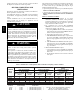
! WARNING FIRE OR ELECTRICAL SHOCK HAZARD Failure to follow this warning could result in personal injury, death, or property damage. If field--supplied manual disconnect switch is to be mounted on furnace casing side, select a location where a drill or fastener cannot damage electrical or gas components. A03221 Fig. 26 -- Field--Supplied Electrical Box on Furnace Casing 1. Select and remove a hole knockout in the casing where the electrical box is to be installed.
312A See notes 2, 5, 8, 10, 11 and 12 on the page following these figures See notes 1, 2, 3, 4, 6, 8, 9, 10, 12, 13 and 15 on the page following these figures A03179 A03178 Fig. 27 -- Two--Stage Furnace with Two--Speed Air Conditioner Fig. 29 -- Two--Stage Furnace with Two--Speed Heat Pump (Dual Fuel) See notes 1, 2, 4, 11, 14, 15, and 16 on the page following these figures See notes 1, 2, 4, 6, 7, 9, 10, 11, and 15 on the page following these figures A03180 A03181 Fig.
312A 7 See notes 2, 11, and 12 on the page following these figures See notes 1, 2, 3, 4, 12, 13, 14, 15, and 17 on the page following these figures A03182 A03183 Fig. 31 -- Dual Fuel Thermostat with Two--Stage Furnace and Two--Speed Heat Pump Fig. 32 -- Two--Stage Thermostat with Two--Stage Furnace and Two--Speed Air Conditioner See notes 1 and 2 on the page following these figures A03184 Fig.
SETUP SWITCHES LOW-HEAT ONLY AND BLOWER OFF-DELAY TRANSFORMER 24-VAC CONNECTIONS 0.5-AMP024 VAC R PL1 - LOW VOLTAGE MAIN HARNESS CONNECTOR FUSE 3-AMP LE SEC-2 PL3 NEUTRAL-L2 PL1 EAC-2 D SEC-1 US C LED OPERATION & DIAGNOSTIC LIGHT PLT HUM ACRDJ TEST/TWIN STAT 3-AMP FUSE 1 2 3 Y1 DHUM G COM WW1 Y/Y2 24V HUMIDIFIER TERMINAL (24-VAC 0.5 AMP MAX.
WARNING CARBON MONOXIDE POISONING HAZARD Failure to follow this warning could result in personal injury or death. hood equipped appliances in accordance with the NFCG or the CAN/CSA--B149.1--05, local building codes, and furnace and vent manufacturers’ instructions. The following information and warning must be considered in addition to the requirements defined in the NFGC or the CAN/CSA--B149.1--05.
CHIMNEY INSPECTION CHART For additional requirements refer to the National Fuel Gas Code NFPA 54/ANSI Z223.1 and ANSI/NFPA 211 Chimneys, Fireplaces, Vents, and Solid Fuel Burning Appliances in the U.S.A. or to the Canadian installation Code CSA-B149.1 in Canada. Crown condition: Missing mortar or brick? Rebuild crown. Yes No 312A Is chimney property lined with clay tile liner? No Yes Is liner and top seal in good condition? No Repair liner or top seal or reline chimney as necessary.
Table 8 – Combined Appliance Maximum Input Rating in Thousands of BTUH per Hour VENT HEIGHT (FT) 6 8 10 15 20 30 INTERNAL AREA OF CHIMNEY (SQ. IN.) 12 19 28 38 74 119 178 257 80 130 193 279 84 138 207 299 NR 152 233 334 NR NR 250 368 NR NR NR 404 Table 9 – Minimum Allowable Input Rating of Space--Heating Appliance in Thousands of BTUH per Hour VENT HEIGHT (FT) INTERNAL AREA OF CHIMNEY (SQ. IN.
312A causing condensation and corrosion in the furnace and/or venting system. Derating is permitted only for altitudes above 2000 ft 3. Adjust the air temperature rise to the midpoint of the rise range or slightly above. Low air temperature rise can cause low vent gas temperature and potential for condensation problems. 4. Set the thermostat heat anticipator or cycle rate to reduce short cycling.
2A SEE NOTES: 1,2,4,5,7,8,9 on the page following these figures SEE NOTES:1,2,3,4,5,7,8,9 on the page following these figures. A03211 A03212 Fig. 39 -- Downflow Application--Vent Elbow Up Fig. 41 -- Downflow Application--Vent Elbow Up then Right SEE NOTES: 1,2,4,7,8,9 on the page following these figures A03213 Fig. 42 -- Horizontal Left Application -- Vent Elbow Left SEE NOTES: 1,2,4,5,6,7,8,9,10 on the page following these figures A03207 Fig.
SEE NOTES: 1,2,4,7,8,9 on the page following these figures SEE NOTES: 1,2,4,5,7,8,9 on the page following these figures A03218 A03216 Fig. 46 -- Horizontal Left Application -- Vent Elbow Right 312A Fig. 44 -- Horizontal Right Application -- Vent Elbow Right SEE NOTES: 1,2,4,5,7,8,9 on the page following these figures SEE NOTES: 1,2,4,5,7,8,9 on the page following these figures A03215 A03219 Fig. 45 -- Horizontal Left Application -- Vent Elbow Up Fig.
Caution!! For the following applications, use the minimum vertical heights as specified below. For all other applications, follow exclusively the National Fuel Gas Code FURNACE ORIENTATION VENT ORIENTATION Downflow Vent elbow left, then up Fig. 40 Horizontal Left Horizontal Left Horizontal Left Downflow Downflow Vent elbow right, then up Fig. 43 Vent Elbow up Fig. 44 Vent elbow right Fig. 45 Vent elbow up then left Fig. 38 Vent elbow up, then right Fig.
312A A04130 Fig. 52 -- Hammer and Screwdriver Used for Knockout A04128 Fig. 50 -- Rounded End of Knockout A04131 Fig. 53 -- Remove Knockout with Hammer ! CAUTION BURN HAZARD Failure to follow this caution may cause personal injury. Hot vent pipe is within reach of small children when installed in downflow position. See the following instruction. A04129 Fig.
In Canada: Per section 8.24.2 of the CAN/CSA--B149.1--05, any listed mechanical venter may be used, when approved by the authority having jurisdiction. Select the listed mechanical venter to match the Btuh input of the furnace being vented. Follow all manufacturer s installation requirements for venting and termination included with the listed mechanical venter. 1. Purge gas lines after all connections have been made. 2. Check gas lines for leaks.
Table 10 – 2--Stage Furnace Setup Switch Description SETUP SWITCH NO. SWITCH NAME NORMAL POSITION SW--- 1 Adaptive Heat Mode OFF SW--- 2 Blower OFF delay ON or OFF SW--- 3 Blower OFF delay ON or OFF DESCRIPTION OF USE When OFF, allows 2--- stage operation with a single stage thermostat. Turn ON when using 2 stage thermostat to allow Low Heat opera--tion when R to W/W1 closes and High Heat operation when R to W/W1 and W2 close. Control blower OFF delay time. Used in conjunction with SW--- 3.
c. Measure time (in sec) for gas meter to complete 1 revolution and note reading. The 2 or 5 cubic feet dial provides a more accurate measurement of gas flow. d. Refer to Table 12 for cubic ft of gas per hr. e. Multiply gas rate cu ft/hr by heating value (Btuh/cu ft) to obtain input. If clocked rate does not match required input from Step 1, increase manifold pressure to increase input or decrease manifold pressure to decrease input. Repeat steps b through e until correct low heat input is achieved.
312A Table 12 – Gas Rate (cu ft/hr) SECONDS FOR 1 REVOLUTION 10 11 12 13 14 15 16 17 18 19 20 21 22 23 24 25 26 27 28 29 30 31 32 33 34 35 36 37 38 39 40 41 42 43 44 45 46 47 48 49 1 C U FT 360 327 300 277 257 240 225 212 200 189 180 171 164 157 150 144 138 133 129 124 120 116 113 109 106 103 100 97 95 92 90 88 86 84 82 80 78 76 75 73 2 C U FT 720 655 600 555 514 480 450 424 400 379 360 343 327 313 300 288 277 267 257 248 240 232 225 218 212 206 200 195 189 185 180 176 172 167 164 160 157 153 150 147
If clocked rate does not match required input from Step 1, increase manifold pressure to increase input or decrease manifold pressure to decrease input. Repeat steps b through e until correct high heat input is achieved. Re--install high--heat regulator seal cap on gas valve. 8. Set high heat temperature rise. Jumper R to W/W1 and W2 to check high--gas--heat temperature rise. Do not exceed temperature rise ranges specified on furnace rating plate for high heat.
Table 14 – 2--Stage Furnace Blower OFF delay Setup Switch DESIRED HEATING MODE BLOWER OFF DELAY (SEC.) 90 120 150 180 SETUP SWITCH SW---2 OFF OFF ON ON SETUP SWITCH SW---3 OFF ON OFF ON THERMOSTAT SUBBASE TERMINALS WITH THERMOSTAT REMOVED (ANITICIPATOR, CLOCK, ETC., MUST BE OUT OF CIRCUIT.) HOOK-AROUND AMMETER 312A R Y W G 10 TURNS FROM UNIT 24-V CONTROL TERMINALS EXAMPLE: 5.0 AMPS ON AMMETER 10 TURNS AROUND JAWS = 0.5 AMPS FOR THERMOSTAT ANTICIPATOR SETTING A96316 Fig. 56 -- Amp.
Step 5 — Checklist 312A 1. Put away tools and instruments. Clean up debris. 2. Verify that switches for LHT and OFF--DELAY are blower OFF--DELAY are selected as desired. 3. Verify that blower and burner access doors are properly installed. 4. Cycle test furnace with room thermostat. 5. Check operation of accessories per manufacturer fs instructions. 6. Review User’s Guide with owner. 7. Attach literature packet to furnace.
Table 15 – Orifice Size and Manifold Pressure for Gas Input Rate (Tabulated Data Based on 22,000 Btuh High--Heat/14,500 Btuh for Low--Heat per Burner, Derated 4% for Each 1000 Ft Above Sea Level) ALTITUDE RANGE (FT) 312A U.S.A. and Canada 0 to 2000 ALTITUDE RANGE (FT) U.S.A. and Canada U.S.A. Altitudes 2001 to 3000 or Canada Altitudes 2001 to 4500 ALTITUDE RANGE (FT) U.S.A. Only 3001 to 4000 ALTITUDE RANGE (FT) U.S.A. Only 4001 to 5000 ALTITUDE RANGE (FT) U.S.A. Only 5001 to 6000 AVG.
Table 15 -- Orifice Size and Manifold Pressure for Gas Input Rate (cont.) (Tabulated Data Based on 22,000 Btuh High--Heat/14,500 Btuh for Low--Heat per Burner, Derated 4% for Each 1000 Ft Above Sea Level) U.S.A. Only 6001 to 7000 ALTITUDE RANGE (FT) U.S.A. Only 7001 to 8000 ALTITUDE RANGE (FT) U.S.A. Only 8001 to 9000 ALTITUDE RANGE (FT) U.S.A. Only 9001 to 10,000 AVG. GAS HEAT VALUE AT ALTITUDE (BTUH/CU FT) 675 700 725 750 775 800 825 850 AVG.
Table 16 – Orifice Size and Manifold Pressure for Gas Input Rate (Tabulated Data Based on 21,000 Btuh High--Heat/14,500 Btuh for Low--Heat Per Burner, Derated 4% for Each 1000 Ft Above Sea level) ALTITUDE RANGE (FT) 312A U.S.A. and Canada 0 to 2000 ALTITUDE RANGE (FT) U.S.A. and Canada U.S.A. Altitudes 2001 to 3000 or Canada Altitudes 2001 to 4500 ALTITUDE RANGE (FT) U.S.A. Only 3001 to 4000 ALTITUDE RANGE (FT) U.S.A. Only 4001 to 5000 ALTITUDE RANGE (FT) U.S.A. Only 5001 to 6000 AVG.
ALTITUDE RANGE (FT) U.S.A. Only 6001 to 7000 ALTITUDE RANGE (FT) U.S.A. Only 7001 to 8000 AVG. GAS HEAT VALUE AT ALTITUDE (BTUH/CU FT) 675 700 725 750 775 800 825 850 AVG. GAS HEAT VALUE AT ALTITUDE ) 650 675 700 725 750 775 800 825 Orifice No. 44 45 46 47 47 48 48 48 0.58 Manifold Pressure 3.3/1.6 3.7/1.8 3.6/1.7 3.8/1.8 3.5/1.7 3.8/1.8 3.6/1.7 3.3/1.6 625 650 675 700 725 750 775 Orifice No. 45 46 47 47 48 48 49 0.58 Manifold Pressure 3.7/1.8 3.6/1.7 3.8/1.8 3.5/1.7 3.7/1.8 3.5/1.7 3.8/1.
! CAUTION UNIT OPERATION HAZARD Failure to follow this caution may result in improper unit operation or failure of unit components. Label all wires prior to disconnection when servicing controls. Wiring errors can cause improper and dangerous operation. 312A Step 1 — Introduction GENERAL These instructions are written as if the furnace is installed in an upflow application.
3. Check electrical connections for tightness and controls for proper operation each heating season. Service as necessary. 4. Inspect burner compartment before each heating season for rust, corrosion, soot or excessive dust. If necessary, have furnace and burner serviced by a qualified service agency. 5. Inspect the vent pipe/vent system before each heating season for rust, corrosion, water leakage, sagging pipes or broken fittings. Have vent pipes/vent system serviced by a qualified service agency. 6.
Fig.
CAUTION ! CUT HAZARD Failure to follow this caution may result in personal injury. Sheet metal parts may have sharp edges or burrs. Use care and wear appropriate protective clothing, safety glasses and gloves when handling parts and servicing furnaces. Media cabinet filter procedures: NOTE: Media Cabinet is included with two--stage furnace. Table 17 – Filter size information (in.
16. Reinstall control box assembly in furnace. ! CAUTION UNIT DAMAGE HAZARD Failure to follow this caution may result in shortened heat exchanger life. 312A Heating fan speed(s) MUST be adjusted to provide proper air temperature rise as specified on the rating plate. Recommended operation is at the midpoint of the rise range or slightly above. Refer to “SET TEMPERATURE RISE” under START--UP, ADJUSTMENT, and SAFETY CHECK.
1-7/8” A01026 Fig. 60 -- Igniter Position -- Top View 312A a. Remove metal screw fitting from wire brush to allow insertion into cable. b. Insert the twisted wire end of brush into end of spring cable, and crimp tight with crimping tool or crimp by striking with ball--peen hammer. TIGHTNESS IS VERY IMPORTANT. NOTE: The materials needed in item 9 can usually be purchased at local hardware stores. (1.) Attach variable--speed, reversible drill to the end of spring cable (end opposite brush). (2.
312A control CPU, transformer TRAN, inducer motor IDM, blower motor BLWM, hot--surface igniter HSI, and gas valve GV. 1. Two--Stage Heating (Adaptive mode) with Single--Stage Thermostat (See Fig. 24 or 33 for thermostat connections) NOTE: The low--heat only switch (LHT) selects either the low--heat only operation mode when ON, (see item 2. below) or the adaptive heating mode when OFF in response to a call for heat. (See Fig. 34.
When the thermostat is satisfied, the R--to--G and--Y circuits are opened. The outdoor unit will stop, and the furnace blower motor BLWM will continue operating on the COOL speed for an additional 90 seconds. Jumper Y/Y2 to DHUM to reduce the cooling off--delay to 5 seconds. (See Fig. 25.) b. Single--Stage Thermostat and Two--Speed Cooling (Adaptive Mode) (See Fig.
312A b. High cooling --When the R--to--G--and--Y/Y2 circuit is closed and there is a demand for dehumidification,the furnace blower motor BLWM will drop the blower speed from COOL to HI HEAT for a maximum of 10 minutes before reverting back to COOL speed. If there is still a demand for dehumidification after 20 minutes, the furnace control CPU will drop the blower speed back to HI HEAT speed. This alternating 10--minute cycle will continue as long as there is a call for cooling. c.
YES Go to section below for the status code that was flashed. Determine status code. The status code is a 2 digit number with the first digit determined by the number of short flashes and the second digit by the number of long flashes? YES Is LED status light blinking ON/OFF slowly with a combination of short and long flashes? NO Is LED status light blinking rapidly without a pause? Is LED status light on? START YES NO YES NO NO NO NO Replace furnace control.
31 HIGH-HEAT PRESSURE SWITCH OR RELAY DID NOT CLOSE OR REOPENED - Check for: - Control relay may be defective. - Gas valve is miswired. - See status code 32. 24 SECONDARY VOLTAGE FUSE IS OPEN Check for: - Short circuit in secondary voltage (24V) wiring including thermostat leads. Disconnect thermostat leads to isolate short circuit. 23 PRESSURE SWITCH DID NOT OPEN Check for: - Obstructed pressure tube. - Pressure switch stuck closed.
E2007 Bryant Heating & Cooling Systems 7310 W. Morris St. Indianapolis, IN 46231 Printed in U.S.A. Edition Date: 02/07 Manufacturer reserves the right to discontinue, or change at any time, specifications or designs without notice and without incurring obligations. 58 Catalog No.