
System information

19
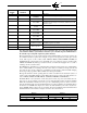
Lockout Messages
Refer to bulletins ED-5101 or E-1101 for a complete list of all ED510 display messages.
Lockout History
Lockout and burner history can be displayed by using the ED510 keypad and display. Refer to Bulle-
tins E-5101 or E-1101.
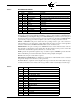
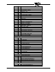
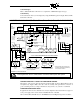
SUGGESTED WIRING DIAGRAM FOR EP160, EP161, EP163, EP165, EP166, EP170 PROGRAMMERS
AUXILIARY DEVICE IN M-D-8 CIRCUIT AT FLAME MONITOR CONTROL
The function of the low fire start and interlock circuit internally in a Fireye Flame-Monitor unit is
accomplished by highly reliable solid state electronic circuitry. This prohibits the connection of
power consuming devices (i.e. lamps, annunciators, relays, timers, etc.) to the D or 8 terminals.
FLAME-MONITOR ELECTRICAL NOISE
In applications with excessive electrical noise, it may be helpful to add an electrical noise suppressor
to the power supply of the control circuit. See Bulletin E-1101 or SN-100.
We recommend Fireye P/N 60-2333 on older EB700 chassis with Engineering Code lower than 3.
Firing Rate
Motor
Switching
Burner Motor
Control Circuit
Firing Rate
Motor Switching
(See Insert)
Ignition And Fuel Valve
Control Circuit
Lockout
Alarm Circuit
Plug In
Flame Amplifier
Flame
Rod
or
Photocell
Only
FIREYE
WIRING BASE
TERMINALS
IMPORTANT: A Good Earth Ground is Essential
Disconnect
Means And
Overload
Protection
120 VOLT
50/60 Hz
H
N
*Note: When A Flame Rod or
photocell is used, Jumper S2 To
the green grounding screw lo-
cated on the wiring base.
PURGE
INT.
FLAME
SCANNER
IR or UV
LOW FIRE
START
INT.
RUNNING
INTERLOCK
FUEL VALVE
INTERLOCK
LIMIT OPERATING
SWITCHES
Burner
Switch
RED
BLACK
TYPICAL WIRING ARRANGEMENT FOR PILOT IGNITED BURNER
JUMPER
WIRING ARRANGEMENT FOR
SPARK IGNITED OIL BURNER
WIRING ARRANGEMENT FOR IGNITION TRANSFORMER
& GAS PILOT VALVE FOR SPARK CUTOFF FEATURE
OF EP170 PROGRAMMER
R
W
B
POWER
SUPPLY
FIRING
RATE
MOTOR
POTENTIOMETER
CONTROLLER
FIREYE
TERMINAL
RA1
AUTOLOHI
COM
S2S1
A
8
7
6
5
1312XPDM3L2L1
11
10
GAS
MAIN
FUEL
VALVE(S)
L1 L2 S1 S2
PILOT
VALVE
LOCKOUT
ALARM
IGNITION
TRANSFORMER
BURNER/
BLOWER
MOTOR
RWB
T
T
RH
56 567
IGNITION
TRANSFORMER
GAS PILOT
VALVE
*
S1 S2
IGNITION
OIL
SOLENOID
VALVE
TRANSFORMER
10 X 12 11
Caution: All safety limit switches should be approved as limit controls and should be wired directly in the circuit of the
Flame Safeguard control. The use of electronic switches to close interlock circuits may cause erratic operation.
1
1 REFER TO TIMING CHARTS EARLIER IN THIS
DOCUMENT FOR OPERATION OF TERMINALS 5
AND 6 DURING PTFI AND MTFI
45UV5-1009
SELF-CHECKING
UV SCANNER