
Specifications


2 point method
- The 2 points can be placed anywhere on the map but it is preferable to give the 2
points as wide a spread on the map as possible.
Do not place the 2 points in a horizontal or vertical
line.
3 point method
- (Registered versions only) The 3 points can be placed anywhere on the map. The
preferable locations are towards 3 of the corners.
Do not place the 3 points in a straight line in any
direction.
4 or more points
-
(Registered versions only) The points can be placed anywhere on the map but the
geometry of the points can have a big effect. The preferable locations are 4 points towards each
corner of the map and the rest evenly distributed over the map.
Make sure that the points have a
good spread across the map.
Entering Positions
For any point you can enter either the Latitude/Longitude or the Grid coordinates. You can enter
some points as Lat/Lon and some as Grid coordinates it does not matter.
The Grid coordinate system used will change depending on the selection in the Map Projection
combo box. If there is no standard Grid system for the projection selected then UTM will be used.
When specifying Degrees and decimal Minutes
-
do not put in negative numbers, use the N/S and
E/W to specify the hemisphere quadrant you are in.
Some Grid systems use Zones and the zone must be entered, other Grid systems do not use zones
and this field will be disabled. For UTM the zone consists of a number and a letter, only the number
part is required, the letter part cannot be entered.
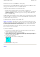
Click on the Point 1 tab (the mouse pointer will now have a number 1 on it). Position the cross hairs
over the known point and click the left mouse button. The point coordinates are entered into the
fields. Now enter the known latitude and longitude of that point or the Grid coordinate, if you enter
both only the Lat/Lon position will be used.
Click on the point 2 tab (the mouse pointer will now have a 2 on it), position the cross hairs over the
2nd known point and click the left mouse button. The point coordinates are entered into the fields.
Enter the known position of that point.
The other points (3 to 9) are handled in the same manner.
A calibration point can be
excluded
from inclusion in the calibration by unchecking the box next to
the x/y coordinate.
Press the Save button, you need to specify a map name, the extension MAP must be used. The map
file stores the name you gave the map, the coordinates of the calibration points and the location and
name of the image file. Later it will also store the Map Features and Map Comments.
To display a map use the
Load Map File
option on the Load menu.
NOTE
: The location of the Map image file is stored within the MAP file. If you move the image
file and try to load the map you will get an error message and be asked if you want to browse the
hard disk to find the image. If you do find the image simple save the map to save the new location of
the image in the map file.
Image Types Supported
Page
109
of
252
OziExplorer Help Contents