
Installation guide


Appendix A – Using the Troubleshooting Screens 89
$SSHQGL[$ - 8VLQJWKH7URXEOHVKRRWLQJ6FUHHQV
Because the Setup Wizard is designed to be a simple step by step process to enable the Duo module to start
scoring quickly, there are several advanced features and diagnostic tools that are contained in the Troubleshooting
screens. These tools will allow you to set and review all aspects of the Duo hardware’s behavior.
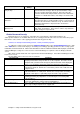
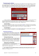
Checking the Machine Connections
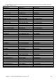
Options 1 and 2 of the Troubleshooting screen allow you to review and test the Pinsetter connection Inputs and
Outputs that are used by the Duo Hardware Module to control the Pinsetter. Depending of the Pinsetter model, not all
the options shown below will be available and this screen will change depending on the Pinsetter Model Type
selected in the Setup Wizard.
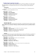
When testing some of the Input or Output connections, a corresponding LED on the Duo Camera Module (If
fitted) will also be lit to show that the command has been received.