
Installation guide

Chapter 2: Run the Cables – Type A 24
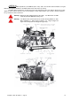
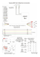
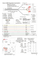
AMF 82-70 with XOP Chassis
Run both the DMO-70XOP and DME-70XOP cables from the Duo Camera Module, along the Ball Track, up
the kickback, to a location near the A&MC Box.
The DMO & DME cables then each consist of three separate cables:
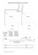
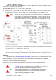
A. The First cable is run to the A&MC box located on the curtain wall. Again, the start contact is wired in series to
the managers control switch on AMC Pin 5 and the cycle contact is wired in parallel across AMC pins 1 & 2 to the
cycle button from the ball return. The Foul signal is also wired to the AMC box across AMC pins 7 & 8.
Note: The Duo unit’s start contacts must be connected in series (in line) not in parallel with
(across) the manager’s control switch. This is to ensure that when the manager’s
control switches are switched off the pinsetter will turn off. Normal operation will see
the Manager’s control switch turned on, the pinsetter will turn on and off with the
games bowled. If, however, there is an urgent need to turn the pinsetter off it can be
done quickly using the Manager's control switches.
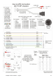
B. The second cable is run to the XOP control chassis, where the existing cable to the old Accuscore system is cut
and a four pin connector is fitted, as per the diagram below. This allows APS commands to be passed from the
Duo units to the XOP chassis. The APS commands allow more advanced pinsetter functions such as short strike
cycle, sweep reverse on 1
st
ball miss and 7 – 10 pick off.
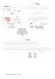
C. The third cable is run to the masking unit, where it is connected across the 2
nd
Ball light. Check the polarity of the
connection by making sure that the 2
nd
Ball Indicator on the Duo Camera unit comes on when the pinsetter is on
second ball.
Important!
The take data delay in the Fine Tune the Scoring Setup screen must be set to a allow enough time for the
score to be taken and the APS input to the XOP chassis to be driven prior to the pinspotter table starting to move.
The default setting is 3.0 seconds. The XOP Chassis must receive the APS scoring input prior to the table
operating, so that any advanced functions such sweep reverse can occur if necessary. If the table starts moving, it
is too late for any advanced commands to be received.
This Take Data Delay should be set as long as possible to give the maximum time for any unsteady pins to
fall, but not too long so that the MK expander times out and ignores 7-10 pick off or short strike cycles.
Note: Make sure that the Pinsetter Model Type in the Setup Wizard is set to AMF
82_70MP. The MP Chassis and the XOP Chassis behave in the same way, so
the one Pinsetter Model Type will operate both types of chassis.
Tip: Some pinspotters have the XOP chassis fitted, but have not been re-wired to
enable reversing of the sweep motor. It is possible to enable or disable the
sweep reverse function for the APS in the Check Pinsetter Connections
screen in the troubleshooting menu of the Duo.