
Installation guide


Chapter 2: Run the Cables – Type A 12
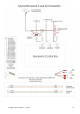
Type A Systems
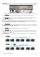
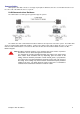
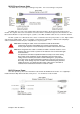
For each pair of lanes in a standard Type A installation there are five communications cables:
1. LLAN This cable runs from the Duo CPU module to the Duo Camera module. Another
LLAN cable is then run from the Duo Camera module to the optional wired connection for the
Bowler’s Keypad. This cable supplies both power and communications.
2. DCC This cable runs from the Duo CPU module to the Duo Camera module. This cable
supplies video signal from the camera.
3. DNC This optional cable runs from the Duo CPU module to a network switch in order to
gain communications to the Center Command front desk software.
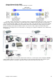
4. DMO This cable runs from the Duo Camera module to the location on the odd lane
pinspotter where the Duo system can tell the machine to turn on and cycle. The location and
configuration of this cable with change according to the model of pinspotter installed. Please
refer to the Machine Connection section of this manual for further information on your type of
pinspotter.
5. DME This cable runs from the Duo Camera module to the location on the even lane
pinspotter where the Duo system can tell the machine to turn on and cycle. The location and
configuration of this cable with change according to the model of pinspotter installed. Please
refer to the Machine Connection section of this manual for further information on your type of
pinspotter.
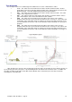
After all cables have been run, they should all be checked to make sure that they are not in danger of being cut
by any moving parts in the pinspotter, or by a ball hitting them in the ball track area under the lanes. In addition, all
the cables should be tied together at the Duo Camera Module and securely tied up out of the way of any balls
travelling past on the ball track.