
Installation Guide

3
NOTE: Clean adhesive from the surface of the floor frequently, using the recommended adhesive cleaner. Urethane
adhesives become extremely difficult to remove when cured. Do not use 3M Scotch-Blue
™
2080 Tape before adhesive
is removed from the surface. Use clean towels, changed frequently, to prevent haze and adhesive residue.
• Check for a tight fit between all edges and ends of each plank. End-joints of adjacent rows should be staggered 4˝-6˝
(10-15 cm) when possible, to ensure a more favorable overall appearance.
• To eliminate minor shifting or gapping of product during installation, use 3M Scotch-Blue
™
2080 Tape to hold the
planks together. After installation is complete, remove all of the 3M Scotch-Blue
™
2080 Tape from the surface of the
newly installed flooring. Do not let the tape remain on the flooring longer than 24 hours. Avoid the use of masking or
duct tape, which leaves an adhesive residue and may damage the finish.
• If necessary, use weights to flatten boards with bows until adhesive cures, in order to prevent hollow spots. Boards
that cannot be flattened should be cut in length to reduce the bow, or not used.
• Be sure not to spread adhesive too far ahead of your work area.
• Complete the installation using this same technique for the remainder of the floor.
• Avoid heavy foot traffic on the floor for at least 24 hours. Lift the furniture or fixtures back into place after 24 hours.
STEP 3
(Staple down Installations)
• Select a board to begin installation of the first row using the longest boards available.
• Starting from the LEFT with the tongue facing the wall, carefully place the first board in place. Use wedges or 1/4˝
(6 mm) scrap along the wall to hold plank in place while allowing the required expansion space.
• Align the next piece by overlapping the end of the first board so that the joint is tight when the board lays flat. Some
slight adjustment of the board may be necessary to assure a tight fit.
• Again, place wedges or 1/4˝ (6 mm) scrap as necessary to restrain movement and maintain expansion zone.
• Continue in this manner until the first row is complete.
• Cut the final board to length allowing the necessary expansion zone.
(Mechanically Fastened/Staple-Down Installations)
• Use the longest, straightest boards available for the first two rows. For random and alternate width products, use the
widest plank for the first row. Align groove of first row on chalk line. The tongue should be facing the starting wall.
Pre-drill 1/2˝ (13 mm) from back (tongue) edge, 1˝-2˝ (2.5-5 cm) from each end, and at 6˝ (15 cm) intervals when
possible. Fasten using 4 or 6d finishing nails or 1˝ (2.5 cm) pneumatic finish nails/brads. Countersink the nails.
• Pre-drill and blind-nail at a 45° angle through the groove of the first row every 1˝-2˝ (2.5-5 cm) from the ends and
spaced in 3˝-4˝ (7.6-10 cm) intervals. Countersink nails to ensure flush engagement of groove with the following
row(s). Continue blind nailing using this method with following rows until stapler can be used. Alternatively use a
pneumatic finish nailer and install nails/brads at the same intervals with a minimum length of 1˝ (2.5 cm).
• End-joints of adjacent rows should be staggered a minimum of 4˝-6˝ (10-15 cm) when possible, to ensure a more
favorable overall appearance.
STEP 4: Installing the Floor
(Mechanically Fastened/Staple-Down Installations)
• Always use the recommended stapler for the specific product being installed (see “Installation Applications”). Use a
minimum 1˝ (2.5 cm) staple recommended by the stapler manufacturer, 1˝-2˝ (2.5-5 cm) from the ends spaced at
3˝-4˝ (8-10 cm) intervals.
• Set compressor at 70 PSI. If groove damage occurs, lower air pressure.
• Fasten several sacrificial boards to the floor. At least two boards, stapled side by side, must be used to indicate
proper machine adjustments.
• Check for surface damage, air pressure setting, groove damage, edge blistering, etc. before proceeding. Make all
adjustments and corrections before installation begins. Once proper adjustments have been made, remove and
destroy the boards.
• Install the remainder of the floor working from several cartons.
• The last 1-2 rows will need to be face-nailed when clearance does not permit blind nailing with a stapler or a brad
nailer. Pre-drill and face-nail or pneumatically nail on the groove side, following the nailing pattern used for the first
row.
STEP 5: Installing Remaining Rows
(All Installations)
• Begin the second row with the cut piece from the first row. If the cut piece is shorter than 8˝ (20 cm) do not use it.
Instead, begin with a new board that exceeds 8˝ (20 cm) in length and allows 6˝ (15 cm) spacing between the end
joints.
• Place the first board in place by angling it up slightly, pushing forward and interlocking the side tongue. Slide the
board to the LEFT as necessary to align the edges of the end joint.
• Carefully push the board down until tongue and groove lock together on the side and ends.
• A slight tap with a tapping block may be necessary to complete the interlock.
• Restrain the movement of the board by installing a wedge in the expansion zone.
• Install all remaining boards and rows in the same manner.
• Cut the last board to size, allowing for the expansion zone, and install as above.
• If necessary, complete the tight fit by tapping the board into place with a pull bar.
• Whenever practical, use cut pieces from previous rows as a starter board to reduce waste.
• Maintain 6˝ (15 cm) spacing between end joints after the first four rows for best appearance.
STEP 6: Installing Final Row
(All Installations)
• The last row may need to be cut lengthwise (ripped).
• Place the row of planks to be fit on top of the last row of installed planks. Use a piece of plank as a scribe to trace the
contour of the wall.
• Mark where the board will be cut. If the fit of the wall is simple and straight, just measure for the correct fit and cut
• After the last row is cut, use the pull bar to tighten the joint.
STEP 7: Installing Under a Door Jamb
(All Installations)
• Installations of locking engineered floors under moldings, such as a door jamb, may require that the top lip of the
groove on the end be reduced in size.
• Using a small plane or knife plane, shave off the ledge off the groove.
• After the groove edge has been trimmed, place the board into place and tighten with a pull bar to test for fit. The
installer must be certain that the proper expansion space is maintained and the flooring is not pinched.
• If fit is incorrect, trim as necessary.
• Place a bead of recommended wood glue on the bottom lip of the groove.
• Reinsert the tongue into the groove and tighten the board with a pull bar. Hold the board in place with painter’s
tape (3M Scotch-Blue
™
2080 Tape) until the glue is dry. Do not use masking tape or duct tape, as the finish may be
damaged.
Scotch-Blue is a trademark of 3M.
All other trademarks are owned by AHF, LLC, or its subsidiaries or affiliates. © 2020 AHF, LLC.
AHF Products, 3840 Hempland Road, Mountville, PA 17554
WF-1258-1120
STEP 8: Completing the Installation
(All Installations)
• Remove all wedges and tape if used.
• Clean floor with the recommended hardwood flooring cleaner.
• Trim all underlayment and install, or re-install, all base and/or quarter round moldings. Nail moldings into the wall,
not the floor. Inspect the floor, filling all minor gaps with the appropriate blended filler.
• If the floor is to be covered, use a breathable material such as cardboard. Do not cover with plastic.
• Leave warranty and floor care information with the owner. Advise them of the product name and code number of the
flooring they purchased.
• To prevent surface damage, avoid rolling heavy furniture and appliances on the floor. Use plywood, hardboard or
appliance lifts if necessary. Use protective castors/castor cups or felt pads on the legs of furniture to prevent damage
to the flooring.
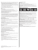
TRANSITION AND WALL MOLDINGS
• Reducer Strip: A teardrop shaped molding used around fireplaces, doorways, as a room divider, or as a transition
between hardwood flooring and adjacent thinner floor coverings. Fasten down with adhesive, small nails or double-
faced tape.
• Threshold: A molding undercut for use against sliding door tracks, fireplaces, carpet, ceramic tile, or existing
thresholds to allow for expansion space and to provide a smooth transition in height difference. Fasten to subfloor
with adhesive and/or nails through the heel. Predrill nail holes to prevent splitting.
• Stair Nosing: A molding undercut for use as a stair landings trim, elevated floor perimeters, and stair steps. Fasten
down firmly with adhesive and nails or screws. Predrill nail holes to prevent splitting.
• Quarter Round: A molding used to cover expansion space next to baseboards, case goods, and stair steps. Predrill
and nail to the vertical surface, not into the floor.
• Combination Base and Shoe: A molding used when a base is desired. Used to cover expansion space between the
floor and the wall. Predrill and nail into the wall, not the floor.
• T-Molding: A molding used as a transition piece from one rigid flooring to another of similar height or to gain
expansion spaces. Fasten at the heel in the center of the molding. Additional rigid support may need to be added to
the heel of the molding dependent upon the thickness of the goods covered. Do not use this molding as a transition
to carpet.
INSTALLERS – ADVISE YOUR CUSTOMER OF THE FOLLOWING
Seasons: Heating and Non-heating
Recognizing that hardwood floor dimensions will be slightly affected by varying levels of humidity within your building,
care should be taken to control humidity levels within the 30-50% range. To protect your investment and to assure that
your floors provide lasting satisfaction, we have provided our recommendations below.
• Heating Season (Dry): A humidifier is recommended to prevent excessive shrinkage in hardwood floors due to low
humidity levels. Wood stoves and electric heat tend to create very dry conditions.
• Non-Heating Season (Humid, Wet): Proper humidity levels can be maintained by use of an air conditioner,
dehumidifier, or by turning on your heating system periodically during the summer months. Avoid excessive
exposure to water from tracking during periods of inclement weather. Do not obstruct in any way the expansion joint
around the perimeter of your floor.
Damage caused by failing to maintain the proper humidity levels is not manufacturing related and will void the
floor’s warranty.
NOTE: Final inspection by the end-user should occur from a standing position.
FLOOR REPAIR
• Minor damage can be repaired with a Bruce
®
touch-up kit or acrylic wood filler. Major damage will require board
replacement, which can be done by a professional floor installer.
• Instructions for the board replacement can be found at www.hardwoodexpert.com, our technical website.
Reducer Strip Threshold Stair Nosing Quarter Round T-Molding