
Owner`s manual
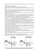
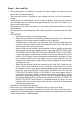

Step 1 – Securing the Cast Burner to the
Base (Burner Mount Bar)
Place base upside down on an even sur-•
face. The wider ring of the base should be
facing downward.
Locate the burner mount bar stretching •
across the narrower ring of the base.
Remove the nut from the bottom of the cast •
burner.
From the bottom side of the burner mount •
bar, place the cast burner into the groove in
the center of the bar. The screw on the cast
burner should fit into the hole in the cen-
ter of the groove. The cast burner should
be positioned towards the side of the base
with the flame viewing hole.
Fasten the cast burner screw securely to •
the burner mount bar with the nut.
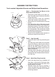
Step 2 – Leg Assembly
Locate the end of each leg containing two •
holes.
Join each leg to the inside of the narrower •
ring of the base so that the two holes of
each leg are aligned with each set of two
holes on the base. When in position, the
legs should be projecting outward from the
center of the base.
Securely fasten each leg to the base with •
two screws per leg. The screws should be
inserted from the outside towards the cen-
ter of the ring.
Step 3 – Metal Base Ring Assembly
Insert the metal base ring in between all •
three legs so that each of the three holes
on the ring match up with each hole at the
projecting end of the legs.
Securely fasten the ring by inserting a •
screw into each hole and tightening. The
screws should be inserted from the center
of the ring outward.
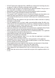
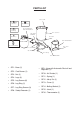
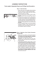
ASSEMBLY INSTRUCTIONS
Tools needed: Adjustable Wrench and Phillips Head Screwdriver
MOUNT BAR
CAST BURNER
NUT
LEGS
SHIELD
SECURITY RING
BASE RING
BASE RING SCREWS
LEG