Installation and Operation Manual X-TMF-5861i-MFM-eng Part Number: 541B111AAG November, 2008 Model 5861i Mass Flowmeter Brooks® Model 5861i
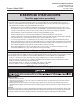
Brooks® Model 5861i Installation and Operation Manual X-TMF-5861i-MFM-eng Part Number: 541B111AAG November, 2008 Essential Instructions Read this page before proceeding! Brooks Instrument designs, manufactures and tests its products to meet many national and international standards. Because these instruments are sophisticated technical products, you must properly install, use and maintain them to ensure they continue to operate within their normal specifications.
Installation and Operation Manual X-TMF-5861i-MFM-eng Part Number: 541B111AAG November, 2008 Brooks® Model 5861i Dear Customer, We appreciate this opportunity to service your flow measurement and control requirements with a Brooks Instrument device. Every day, flow customers all over the world turn to Brooks Instrument for solutions to their gas and liquid low-flow applications.
Installation and Operation Manual X-TMF-5861i-MFM-eng Part Number: 541B111AAG November, 2008 Brooks® Model 5861i THIS PAGE WAS INTENTIONALLY LEFT BLANK
Installation and Operation Manual X-TMF-5861i-MFC-eng Part Number: 541B111AAG November, 2008 Brooks® Model 5861i Section 1 Introduction Paragraph Number Page 1-1 Purpose ............................................................................. 1-1 1-2 Description ........................................................................ 1-1 1-3 Specifications .................................................................... 1-1 2-1 Receipt of Equipment .......................................
Installation and Operation Manual X-TMF-5861i-MFM-eng Part Number: 541B111AAG November, 2008 Brooks® Model 5861i Figures Figure Page 2-1 Model 5861i Dimensions ................................................... 2-3 2-2 "D" Type Connector Pin Arrangement ................................ 2-3 2-3 Maximum Allowable Loop Resistance ............................... 2-5 2-4 Common Electrical Hook-Ups ........................................... 2-7 3-1 Flow Sensor Operational Diagram ...................
Section 1 Introduction Installation and Operation Manual X-TMF-5861i-MFC-eng Part Number: 541B111AAG November, 2008 Brooks® Model 5861i 1-1 Purpose The Brooks® Model 5861i Flowmeter is a mass flow measurement device designed for accurately measuring flows of gases. This instruction manual is intended to provide the user with all the information necessary to install, operate and maintain the Brooks 5861i Mass Flow Meter.
Section 1 Introduction Installation and Operation Manual X-TMF-5861i-MFM-eng Part Number: 541B111AAG November, 2008 Brooks® Model 5861i Power Requirements +15 to +28Vdc @ 90 mA 2.5 watts power consumption max.@28 volts Ambient Temperature Limits Operating: 5 to 65°C (40 to 150°F) Non-Operating: -25 to 100°C (-13 to +212°F) Working Pressure 1500 psi (10.34 MPa) maximum Output Signal 0-5 Vdc into 2000 ohms or greater. Maximum ripple 3 mV. Jumper selectable 4-20 mAdc or 0-20 mAdc.
Section 2 Installation Installation and Operation Manual X-TMF-5861i-MFC-eng Part Number: 541B111AAG November, 2008 Brooks® Model 5861i 2-1 Receipt of Equipment When the equipment is received, the outside packing case should be checked for damage incurred during shipment. If the packing case is damaged, the local carrier should be notified at once regarding his liability. A report should be submitted to the Product Service Department, Brooks Instrument, Hatfield, Pennsylvania 19440-0903.
Section 2 Installation Installation and Operation Manual X-TMF-5861i-MFM-eng Part Number: 541B111AAG November, 2008 Brooks® Model 5861i 2-3 Return Shipment Prior to returning any Brooks equipment to the factory, contact the factory for a Return Materials Authorization Number (RMA#). This can be obtained at Brooks Instrument, Product Service Department, 407 West Vine Street, Hatfield, PA 19440-0903, or call toll free 1-888-554-FLOW (3569). Brooks Instrument 407 W. Vine Street P.O.
Section 2 Installation Installation and Operation Manual X-TMF-5861i-MFC-eng Part Number: 541B111AAG November, 2008 Connection Brooks® Model 5861i "X"Dim. 1/4"Compression Fitting 5.17 131 1/4" Tube VCO 4.71 120 1/4" Tube VCR 5.03 128 3/8"Compression Fitting 3/8" or 1/2" Tube 5.29 134 5.15 VCO 3/8" or 1/2" Tube VCR 131 5.33 135 Figure 2-1 Model 5861i Dimensions PIN NO.
Section 2 Installation Installation and Operation Manual X-TMF-5861i-MFM-eng Part Number: 541B111AAG November, 2008 Brooks® Model 5861i Recommended installation procedures: a. The Model 5861i should be located in a clean dry atmosphere relatively free from shock and vibration. b. Leave sufficient room for access to the electrical components. c. Install in such a manner that permits easy removal if the instrument requires cleaning. d. The Model 5861i Mass Flowmeter can be installed in any position.
Section 2 Installation Installation and Operation Manual X-TMF-5861i-MFC-eng Part Number: 541B111AAG November, 2008 Brooks® Model 5861i 2-7 Electrical Interfacing To insure proper operation the Model 5861i must be connected per Figures 2-2, 2-3, and 2-4 and configured according to Section 2-7. Note: There are several functions on the printed circuit board which are not used by the Model 5861i. Avoid making connections marked in Figure 2-2 which are marked *.
Section 2 Installation Installation and Operation Manual X-TMF-5861i-MFM-eng Part Number: 541B111AAG November, 2008 Brooks® Model 5861i Supply The power of the mass flow meter is connected to Pin 5 (+15 to +28 Vdc) and Pin 9 (supply common) of the D-connector. Refer to Section 1-3 for the power requirements. Note: The length of the wire for the power supply connection (Pins 5&9) must be selected as to insure a minimum of 15 Vdc is available at the mass flow meter.
Section 2 Installation Installation and Operation Manual X-TMF-5861i-MFC-eng Part Number: 541B111AAG November, 2008 Brooks® Model 5861i Notes: 1. Tie cable shields to ground at one end only. 2. Current and voltage outputs may be used simultaneously.
Section 2 Installation Installation and Operation Manual X-TMF-5861i-MFM-eng Part Number: 541B111AAG November, 2008 Brooks® Model 5861i THIS PAGE WAS INTENTIONALLY LEFT BLANK 2-8
Section 3 Operation Installation and Operation Manual X-TMF-5861i-MFC-eng Part Number: 541B111AAG November, 2008 Brooks® Model 5861i 3-1 Theory of Operation The thermal mass flow sensing technique used in the 5861i works as follows: A precision power supply provides a constant power heat input (P) at the heater which is located at the midpoint of the sensor tube.
Section 3 Operation Installation and Operation Manual X-TMF-5861i-MFM-eng Part Number: 541B111AAG November, 2008 Brooks® Model 5861i Figure 3-1 Flow Sensor Operational Diagram 3-2 Operating Procedure a. Apply power to the flowmeter and allow approximately 45 minutes for the instrument to warm-up and stabilize its temperature. b. Turn on the gas supply. c. Shut-off flow to the meter and observe the flowmeter's output signal.
Installation and Operation Manual X-TMF-5861i-MFC-eng Part Number: 541B111AAG November, 2008 Section 3 Operation Brooks® Model 5861i To check zero always mount the flowmeter in its final configuration and allow a minimum of 20 minutes for the temperature of the controller and its environment to stabilize. Using a suitable voltmeter check the flowmeter output signal. If it differs from the factory setting adjust it by removing the lower pot hold plug, which is located closest to the controller body.
Section 3 Operation Installation and Operation Manual X-TMF-5861i-MFM-eng Part Number: 541B111AAG November, 2008 Brooks® Model 5861i Figure 3-2 Model 5861i Calibration Connections * *Note: Not used for a 5861i Figure 3-3 Adjustment Potentiometer Location 3-4 Figure 3-4 Fast Response Adjustment
Section 3 Operation Installation and Operation Manual X-TMF-5861i-MFC-eng Part Number: 541B111AAG November, 2008 Brooks® Model 5861i f. Shut off the flow. Connect the DVM positive lead to flow signal output (pin 2 D-connector) and the negative lead to TP4. Readjust the zero potentiometer for an output of 0mV±2mV as necessary. g. Adjust flow rate for a flow signal output of 50% (2.500V) and measure the flow rate. Calculate the error as a percentage of full scale.
Section 3 Operation Brooks® Model 5861i Installation and Operation Manual X-TMF-5861i-MFM-eng Part Number: 541B111AAG November, 2008 3. Adjust the linearity potentiometer for an output equal to the new TP2 voltage and then repeat step k. Note: The voltage at TP2 can range from -3 to +3 volts, however, it is recommended that this voltage stay between -2.5 and +2.5 volts for proper operation. If the recommended voltage range is exceeded the desired accuracy and/or signal stability may not be achieved.
Installation and Operation Manual X-TMF-5861i-MFC-eng Part Number: 541B111AAG November, 2008 Section 3 Operation Brooks® Model 5861i * Not Used Figure 3-5 PC Board Jumper Location and Function 3-7
Section 3 Operation Installation and Operation Manual X-TMF-5861i-MFM-eng Part Number: 541B111AAG November, 2008 Brooks® Model 5861i THIS PAGE WAS INTENTIONALLY LEFT BLANK 3-8
Installation and Operation Manual X-TMF-5861i-MFC-eng Part Number: 541B111AAG November, 2008 Section 4 Maintenance Brooks® Model 5861i 4-1 General No routine maintenance is required on the Model 5861i other than an occasional cleaning. If an in-line filter is used, the filtering element should periodically be replaced or ultrasonically cleaned. 4-2 Troubleshooting A. System Checks The Model 5861i is generally used as a component in gas handling systems which can be quite complex.
Section 4 Maintenance Brooks® Model 5861i Installation and Operation Manual X-TMF-5861i-MFM-eng Part Number: 541B111AAG November, 2008 Table 4-1 Bench Troubleshooting Trouble Possible Cause Check/Corrective Action Output stays at 0 Volts regardless of flow. Clogged Sensor. Clean sensor. Refer to cleaning procedure. Section 4-2. Output signal stays at a voltage Defective PC Board. greater than 5.000 volts and there is no flow through meter Defective Sensor. Replace PC Board. Refer to Section 4-4.
Section 4 Maintenance Installation and Operation Manual X-TMF-5861i-MFC-eng Part Number: 541B111AAG November, 2008 Brooks® Model 5861i 2. Verify that the process gas connections have been correctly terminated and leak checked. B. Bench Troubleshooting 1. Properly connect the mass flow controller to a +15 to +28 Vdc power supply, and connect an output signal readout device (4-1/2 digit voltmeter recommended) to (Pins 2 and 10 D-connector) (Refer to Figure 2-2).
Section 4 Maintenance Installation and Operation Manual X-TMF-5861i-MFM-eng Part Number: 541B111AAG November, 2008 Brooks® Model 5861i 3. Use a hemostat or tweezers to push a 0.007" dia. piano wire through the flow sensor tube to remove any contamination. For best results push the wire into the downstream opening of the sensor. The sensor tube can be flushed with a non-residuous. A hypodermic needle filled with solvent is a convenient means to accomplish this. 4.
Section 4 Maintenance Installation and Operation Manual X-TMF-5861i-MFC-eng Part Number: 541B111AAG November, 2008 Brooks® Model 5861i 2. Unplug the sensor connector from the PC Board. Remove the two screws securing the bracket (26) and PC Board (28). Remove the bracket and PC Board. 3. Remove the two allen nuts (9) using an 1/8" allen wrench and washers (10) securing the sensor assembly (7). Remove the sensor assembly. Note: Do not attempt to disassemble the sensor assembly. 4.
Section 4 Maintenance Installation and Operation Manual X-TMF-5861i-MFM-eng Part Number: 541B111AAG November, 2008 Brooks® Model 5861i 6. Press the lubricated sensor O-rings (8) into the flowmeter body (1). 7. Install the sensor assembly (7) as shown in Figure 5-1 and secure with the 2 allen nuts (9) and washers (10). Tighten the allen nuts to 10 inch lbs. 8. Install the printed circuit board(28), secure with bracket (26) and 2 screws (27).
Section 4 Maintenance Installation and Operation Manual X-TMF-5861i-MFC-eng Part Number: 541B111AAG November, 2008 Brooks® Model 5861i Table 4-3 Conversion Factors (Nitrogen Base) GAS NAME FORMULA Acetylene Air Allene Ammonia Argon Arsine Boron Trichloride Boron Trifluoride Bromine Pentafluoride Bromine Trifluoride Bromotrifluoroethylene Bromotrifluoromethane f-13B1 1,3-Butadiene Butane 1-Butene CIS-2-Butene Trans-2-Butene Carbon Dioxide Carbon Disulfide Carbon Monoxide Carbon Tetrachloride Carbon Tetr
Section 4 Maintenance Installation and Operation Manual X-TMF-5861i-MFM-eng Part Number: 541B111AAG November, 2008 Brooks® Model 5861i Table 4-3 Conversion Factors (Nitrogen Base) Continued 4-8 GAS NAME FORMULA Hydrogen Hydrogen Bromide Hydrogen Chloride Hydrogen Cyanide Hydrogen Fluoride Hydrogen Iodide Hydrogen Selenide Hydrogen Sulfide Iodine Pentafluoride Isobutane Isobutene Isopentane Krypton Methane Methylacetylene Methyl Bromide 3-Methyl-1-butene Methyl Chloride Methyl Fluoride Methyl Mercaptan
Section 4 Maintenance Installation and Operation Manual X-TMF-5861i-MFC-eng Part Number: 541B111AAG November, 2008 Brooks® Model 5861i Where, P1 = percentage (%) of gas 1 (by volume) P2 = percentage (%) of gas 2 (by volume) Pn = percentage (%) of gas n (by volume) Example: The desired gas is 20% Helium (He) and 80% Chlorine (Cl) by volume. The desired full scale flow rate of the mixture is 20 slpm. Sensor conversion factor for the mixture is: N2 equivalent flow = 20/0.946 = 21.
Section 4 Maintenance Brooks® Model 5861i Installation and Operation Manual X-TMF-5861i-MFM-eng Part Number: 541B111AAG November, 2008 Figure 4-1 Restrictor Element Assembly 4-10 Figure 4-2 Restrictor Element Orientation in Meter Body
Section 4 Maintenance Installation and Operation Manual X-TMF-5861i-MFC-eng Part Number: 541B111AAG November, 2008 Brooks® Model 5861i Table 4-4 Restrictor Selection Guide Based on 00C Standard Reference Temperature **For Hydrogen from 130 slpm to 200 slpm use 3-60 micron restrictor elements. Note: If the Nitrogen equivalent flow is between two sizes, choose the larger size. The Model 5861i Mass Flowmeter utilizes porous metal restrictor assemblies for all full scale flow rates.
Section 4 Maintenance Installation and Operation Manual X-TMF-5861i-MFM-eng Part Number: 541B111AAG November, 2008 Brooks® Model 5861i THIS PAGE WAS INTENTIONALLY LEFT BLANK 4-12
Section 5 Parts List Installation and Operation Manual X-TMF-5861i-MFC-eng Part Number: 541B111AAG November, 2008 Brooks® Model 5861i 5-1 General When ordering parts, please specify: Brooks Serial Number Model Number Part Description Part Number Quantity (Refer to Figure 5-1 and Tables 5-1 and 5-2).
Section 5 Patrs List Brooks® Model 5861i Figure 5-1 Model 5861i Parts Drawing.
Section 5 Parts List Installation and Operation Manual X-TMF-5861i-MFC-eng Part Number: 541B111AAG November, 2008 Brooks® Model 5861i Table 5-1 Model 5861i Replacement Parts List Item No. 1 3 5 6 7 8 9 10 11 19 26 27 28 35 Qty. 1 1 4 1 1 1 1 2 2 2 2 2 2 2 2 2 2 2 2 2 2 1 5 1 1 1 1 37 40 41 45 NS 1 1 2 2 NS 1 NS 1 NS 2 Description Body and Stud Weldment Endblock and Screen Weldment Soc. Hd.
Section 5 Patrs List Brooks® Model 5861i Installation and Operation Manual X-TMF-5861i-MFM-eng Part Number: 541B111AAG November, 2008 Table 5-2 Tool and Spare Part Kits for Model 5861i 5850 Series Service Tool Kit P/N S778D017AAA 5850/5860 Series Break Out Board Assembly P/N S273Z668AAA for D Connector version Permits the complete disassembly of the Model 5861i for servicing. Installs directly between mass flow sensor/ controller and interconnecting cable.
Installation and Operation Manual X-TMF-5861i-MFC-eng Part Number: 541B111AAG November, 2008 Section A CE Certification Brooks® Model 5861i Dansk Brooks Instrument 407 West Vine St. Hatfield, PA 19440 U.S.A. Emne : Tillæg til instruktions manual. Reference : CE mærkning af Masse Flow udstyr Dato : Januar-1996. Brooks Instrument har gennemført CE mærkning af elektronisk udstyr med succes, i henhold til regulativet om elektrisk støj (EMC direktivet 89/336/EEC).
Section A CE Certification Brooks® Model 5861i Installation and Operation Manual X-TMF-5861i-MFM-eng Part Number: 541B111AAG November, 2008 English Brooks Instrument 407 West Vine St. Hatfield, PA 19440 U.S.A. Subject : Addendum to the Instruction Manual. Reference : CE certification of Mass Flow Equipment Date : January-1996. The Brooks (electric/electronic) equipment bearing the CE mark has been successfully tested to the regulations of the Electro Magnetic Compatibility (EMC directive 89/336/EEC).
Installation and Operation Manual X-TMF-5861i-MFC-eng Part Number: 541B111AAG November, 2008 Section A CE Certification Brooks® Model 5861i Français Brooks Instrument 407 West Vine St. Hatfield, PA 19440 U.S.A. Sujet : Annexe au Manuel d’Instructions. Référence : Certification CE des Débitmètres Massiques à Effet Thermique. Date : Janvier 1996.
Section A CE Certification Brooks® Model 5861i Installation and Operation Manual X-TMF-5861i-MFM-eng Part Number: 541B111AAG November, 2008 Italiano Brooks Instrument 407 West Vine St. Hatfield, PA 19440 U.S.A. Oggetto : Addendum al manuale di istruzioni. Riferimento : Certificazione CE dei misuratori termici di portata in massa Data : Gennaio 1996.
Installation and Operation Manual X-TMF-5861i-MFC-eng Part Number: 541B111AAG November, 2008 Section A CE Certification Brooks® Model 5861i Norsk Brooks Instrument 407 West Vine St. Hatfield, PA 19440 U.S.A.
Section A CE Certification Brooks® Model 5861i Installation and Operation Manual X-TMF-5861i-MFM-eng Part Number: 541B111AAG November, 2008 Suomi Brooks Instrument 407 West Vine St. Hatfield, PA 19440 U.S.A. Asia : Lisäys Käyttöohjeisiin Viite : Massamäärämittareiden CE sertifiointi Päivämäärä : Tammikuu 1996 Brooksin CE merkillä varustetut sähköiset laitteet ovat läpäissyt EMC testit (direktiivi 89/336/EEC). Erityistä huomiota on kuitenkin kiinnitettävä signaalikaapelin valintaan.
Installation and Operation Manual X-TMF-5861i-MFC-eng Part Number: 541B111AAG November, 2008 Brooks® Model 5861i THIS PAGE WAS INTENTIONALLY LEFT BLANK
Installation and Operation Manual X-TMF-5861i-MFM-eng Part Number: 541B111AAG November, 2008 Brooks® Model 5861i LIMITED WARRANTY Seller warrants that the Goods manufactured by Seller will be free from defects in materials or workmanship under normal use and service and that the Software will execute the programming instructions provided by Seller until the expiration of the earlier of twelve (12) months from the date of initial installation or eighteen (18) months from the date of shipment by Seller.