
User guide


Brooks
®
Model 5850E
2-5
Section 2 Installation
Installation and Operation Manual
X-TMF-5850E-MFC-eng
Part Number: 541B102AAG
September, 2009
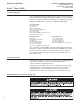
Figure 2-3 Model 5850E Card Edge Connector Hookup Diagram
Figure 2-4. D-Connector Pin Arrangement
PIN NO. FUNCTION COLOR CODE
1 Command Common (Potentiometer Pin "CCW") Black
2 0-5 Volt Signal Output White
3 Not Used Red
4 Valve Off Green
5 +15 Vdc Supply Orange
6 -15 Vdc Supply Blue
7 Valve Test Point Wht/Blk
8 Command Input (Potentiometer Pin "S") Red/Blk
9 Supply Voltage Common Grn/Blk
10 0-5 Volt Signal Common Org/Blk
11 +5 Volt Reference Output (Potentiometer Pin "CW") Blu/Blk
12 Valve Override Blk/Wht
13 Not Used Red/Wht
14 Chassis Ground Grn/Wht
15 Remote Transducer Input* Blu/Wht
*Jumper Selectable
Notes:
1. Cable shield tied to chassis ground
in meter connector. Make no
connection on customer end.
2. All power leads must be connected
to power supply.