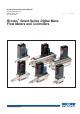
Installation and Operation Manual X-TMF-5800S-MFC-eng PN 541-C-051-AAG November, 2008 Models 5800-S Brooks® Smart-Series Digital Mass Flow Meters and Controllers Brooks Smart Family 1
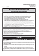
Installation and Operation Manual X-TMF-5800S-MFC-eng PN 541-C-051-AAG November, 2008 Models 5800-S Essential Instructions Read this page before proceeding! Brooks Instrument designs, manufactures and tests its products to meet many national and international standards. Because these instruments are sophisticated technical products, you must properly install, use and maintain them to ensure they continue to operate within their normal specifications.
Installation and Operation Manual X-TMF-5800S-MFC-eng PN 541-C-051-AAG November, 2008 Models 5800-S Dear Customer, We appreciate this opportunity to service your flow measurement and control requirements with a Brooks Instrument device. Every day, flow customers all over the world turn to Brooks Instrument for solutions to their gas and liquid low-flow applications.
Installation and Operation Manual X-TMF-5800S-MFC-eng PN 541-C-051-AAG November, 2008 Models 5800-S Table of Contents Section 1:Introduction ......................................................................................................................................... 5 1.1 Purpose ........................................................................................................................................... 5 1.2 How to use this Manual ................................................
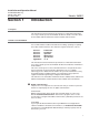
Installation and Operation Manual X-TMF-5800S-MFC-eng PN 541-C-051-AAG November, 2008 Section 1 Models 5800-S Introduction 1.1 Purpose This instruction manual is intended to provide the user with all the information necessary to install, operate and maintain the Brooks Smart series Mass Flow meters 5860S, 5861S, 5863S and controllers 5850S, 5851S, 5853S. 1.2 How to use this Manual It is recommended to read this manual before installing, operating or repairing these Mass Flow Instruments.
Installation and Operation Manual Section 1: Introduction X-TMF-5800S-MFC-eng PN 541-C-051-AAG November, 2008 Models 5800-S Smart Service If you are equipped with primary standard Volumeter calibration equipment or (secondary standard) Brooks Smart Mass Flow Meters, you can use the model 0163 Brooks Smart Service program for (re)configuration, diagnostics, calibration and/or verification.The HART protocol-based commands are listed in a separate.
Installation and Operation Manual Section 1: Introduction X-TMF-5800S-MFC-eng PN 541-C-051-AAG November, 2008 Models 5800-S • Output damping provides a constant scale reading under fluctuating flow rate conditions. Standard factory setting: 0.5 sec. • Output limiting prevents possible damage to delicate acquisition devices by limiting the output to 0-5.25 Vdc on the voltage signal output and 0-21 mA on the current output. An alarm (TTL open collector) signal output is available to the user.
Section 1: Introduction Installation and Operation Manual X-TMF-5800S-MFC-eng PN 541-C-051-AAG November, 2008 Models 5800-S • selectable soft start • adaptive valve control ⇒ Adaptive filtering for signal flow component • Alarms ⇒ Self-diagnostic • EEPROM error • database error • analogue output error ⇒ Out-of-range indications • for analogue set points higher than 100% (controller only) • flow • valve (controller only) • analogue output ⇒ Environmental errors • no gas flow detected • power supply outsid
Installation and Operation Manual X-TMF-5800S-MFC-eng PN 541-C-051-AAG November, 2008 Section 2: Models 5800-S Installation 2.1 General This section contains the procedures for the receipt and installation of the instrument. Do not attempt to start the system until the instrument has been permanently installed. It is extremely important that the start-up procedures be followed in the exact sequence presented.
Installation and Operation Manual Section 2: Installation X-TMF-5800S-MFC-eng PN 541-C-051-AAG November, 2008 Models 5800-S 2.3 Recommended Storage Practice If equipment supplied by Brooks Instrument is to be placed in intermediate or long-term storage, it is recommended that it be: a. Stored within the original shipping container. b. Stored in a sheltered area, under the following conditions: 1) Optimum ambient temperature 21°C (70 °F), maximum 32 °C (90 °F), minimum 7 °C (45 °F),.
Installation and Operation Manual X-TMF-5800S-MFC-eng PN 541-C-051-AAG November, 2008 Section 2: Installation Models 5800-S 2.6 Mechanical Installation (For dimensional drawings see Appendix B: Dimensional drawings) NOTE: When installing the Mass Flow device, care should be taken to prevent foreign materials from entering the instrument’s inlet or outlet. Do not remove the protective end-caps until the actual moment of installation.
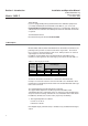
Installation and Operation Manual Section 2: Installation X-TMF-5800S-MFC-eng PN 541-C-051-AAG November, 2008 Models 5800-S 2.8 Electrical Interfacing The installation of Smart TMF includes a 15-pin Sub-D connector. For details of correct installation, see Table 2-1 Table 2-1: Electrical interfacing. Smart TMF Pin (TMF side) 1. 2. 3. 4. 5. 6. 7. 8. 9. 10. 11. 12. 13. 14.
Installation and Operation Manual Section 2: Installation X-TMF-5800S-MFC-eng PN 541-C-051-AAG November, 2008 Models 5800-S common) on the D-connector. If a -15 Vdc power supply is required, pin 6 must be connected and jumper [K2] on the p.c. board must be set the lower position (see Figure 2-2). This is applicable for model 5851S and/or when a Normally Opened (N.O.) control valve is used.
Installation and Operation Manual Section 2: Installation X-TMF-5800S-MFC-eng PN 541-C-051-AAG November, 2008 Models 5800-S pins 14 and 15 are available for connecting the device to the RxD/A- or TxD/A+ lines for RS-232/RS-485 communications. NOTE: Either RS-232 or RS-485 should be specified at the time of ordering. See section 2.7 for details of how to configure the p.c. board. 2.
Installation and Operation Manual Section 2: Installation X-TMF-5800S-MFC-eng PN 541-C-051-AAG November, 2008 Models 5800-S Table 2-2: Dipswitch settings Physical Baud rate layer selection selection RS-232 RS-485 Switch #1 Dipswitch block SW1 Switch Switch Switch #4 #2 #3 Off On 1200 2400 3600 4800 7200 9600 19200 38400 Off On Off On Off On Off On Off Off On On Off Off On On Off Off Off Off On On On On Since Brooks Smart Mass Flow devices are capable of communication immediately after start-up, y
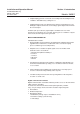
Installation and Operation Manual Section 2: Installation X-TMF-5800S-MFC-eng PN 541-C-051-AAG November, 2008 Models 5800-S 1 8 9 15 D-connector to PC 25-pin (9-pin) 3(2) RxD 2(3) TxD 7(5) Gnd Figure 2-3: RS-232 interconnection of TMF and PC Figure 2-4: RS-485 multidrop interconnection TMFs and PC The RS-485 is essentially a multidrop connection. It allows a maximum of 32 devices to be connected to a computer system. IBM-ompatible PCs are not equipped with RS-485 ports as standard.
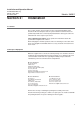
Installation and Operation Manual Section 2: Installation X-TMF-5800S-MFC-eng PN 541-C-051-AAG November, 2008 Models 5800-S Length: 3 m; Length: 6 m; Length: 12 m; part number 124-Z-236-AAA part number 124-Z-237-AAA part number 124-Z-610-AAA READ-OUT SIDE Sub-D 15-pin male THERMAL SIDE Sub-D 15-pin female Figure 2-5: TMF/C to Read-out cable If no digital communication is required, a split cable can be supplied to interconnect the Brooks Microprocessor Control & Read-out Unit, the Smart Mass Flow Met
Installation and Operation Manual Section 2: Installation X-TMF-5800S-MFC-eng PN 541-C-051-AAG November, 2008 Models 5800-S Table 2-3: Electrical interfacing. Smart TMF cable Sub-D (15 c.) Read-out side Computer side sub D (15p) sub D (15p) sub D (25p) sub D (9p) female male female female pin no. pin no. pin no. pin no. 1. 2. 3. 4. 5. 6. 7. 8. 9. 10. 11. 12. 14. 15.
Installation and Operation Manual X-TMF-5800S-MFC-eng PN 541-C-051-AAG November, 2008 Section 3: Models 5800-S Operation 3.1 Operating Procedure 1 Apply power to the Smart Mass Flow device and allow approximately 45 minutes for the instrument to reach a stable temperature. 2 Check the flow reading before turning on the pressurised gas supply. If the flow reading is >0.2% then the instrument should be re-zeroed (see section 3.2). 3 Turn on the gas supply. 4 Regulate flow to 0%.
Installation and Operation Manual X-TMF-5800S-MFC-eng PN 541-C-051-AAG November, 2008 Models 5800-S Section 4: Maintenance 4.1 General No routine maintenance is required on the Smart Mass Flow Meters and Controllers other than occasional cleaning. The in-line filter should periodically be replaced or ultrasonically cleaned. NOTE: If recalibration is required, but the necessary expertise or equipment is not available, the instrument should be returned to the factory. 4.
Installation and Operation Manual X-TMF-5800S-MFC-eng PN 541-C-051-AAG November, 2008 Section 4: Maintenance Models 5800-S necessary, perform the zero adjustment procedure (section 3.2). If the output signal does not zero properly, please contact Brooks Instrument. 2. Connect the instrument to a source of the same gas used for its original calibration. Regulate the Set point to 100% flow and adjust the inlet and outlet pressures to the calibration conditions. Verify that the output signal reaches 5.
Installation and Operation Manual Section 4: Maintenance X-TMF-5800S-MFC-eng PN 541-C-051-AAG November, 2008 Models 5800-S Table 4-1: Troubleshooting Trouble Output stays at zero (regardless of Set point) and there is flow through the meter/controller Flow can not be achieved regardless of Set point. (applicable to MFC) Output signal stays at approx. 5.
Installation and Operation Manual X-TMF-5800S-MFC-eng PN 541-C-051-AAG November, 2008 Section 4: Maintenance Models 5800-S 4.3 Cleaning Procedures When deposition makes it necessary to clean the Smart Mass Flow Controller or Mass Flow Meter, use the following procedures: 1. Remove the unit from the system. 2. Purge with dry nitrogen gas, which removes virtually all particulate matter from the device. Should contamination persist, subject all wetted 1 components to ultrasonic cleaning.
Installation and Operation Manual X-TMF-5800S-MFC-eng PN 541-C-051-AAG November, 2008 Models 5800-S Section 5: Specification PERFORMANCE SPECIFICATIONS Flow Accuracy Repeatability Rangeability Controllability Stability Temperature Sensitivity ± 0.7% of rate and ±0.2% F.S. (at calibration conditions) ± 0.5% of rate and ±0.1% F.S. (optional consult factory) ± 1.0% F.S. for flowrates above 1100 ln/min (for 5863/5853) ± 0.25% of rate 50:1 (within specified accuracy) 100:1 (i.e.
Installation and Operation Manual Section 5: Specification X-TMF-5800S-MFC-eng PN 541-C-051-AAG November, 2008 Mass Flow Controller Model: 5850 S 5851 S 5853 S 3 Models 5800-S Table 5-1: Flow ranges and pressure ratings Brooks Smart Mass Flow Products Mass Flow Flow Ranges N2 Pressure Meter Equivalent Ratings Model: 5860 S 5861 S 2 5863 S Min. f.s. 0.003 20 Max. f.s. 30 100 Unit 1 ln /min. ln /min. Bar 100/300 bar 100 bar 100 2500 ln /min. 70 bar P.E.D. Module H Category S.E.P. S.E.P.
Installation and Operation Manual Section 5: Specification X-TMF-5800S-MFC-eng PN 541-C-051-AAG November, 2008 Models 5800-S Temperature Both ambient and process gas: 0-70 °C. Leak Integrity Outboard: 1 x 10⁻⁹ mbar l/sec. Helium Warm-up time < 10 minutes; 1% F.S. accuracy. Performance within specifications: 45 minutes. Damping Damping from 0 to 10 seconds is possible for the flow output signal(s) * (default setting is 0.5 sec.).
Installation and Operation Manual X-TMF-5800S-MFC-eng PN 541-C-051-AAG November, 2008 Section 5: Specification Models 5800-S 27
Installation and Operation Manual X-TMF-5800S-MFC-eng PN 541-C-051-AAG November, 2008 Models 5800-S Appendix A: Gas Conversion Tables USE OF THE CONVERSION TABLES If a Mass Flow Meter or Controller is operated on a gas other than the gas it was calibrated with, a scale shift will occur in the relationship between the output signal and the mass flow rate as a result of the difference in heat capacities between the two gases.
Installation and Operation Manual X-TMF-5800S-MFC-eng PN 541-C-051-AAG November, 2008 Gas Conversion Table Gasname Acetylene (Ethyne) Air Allene Ammonia Argon Arsine Boron Trichloride Boron Trifluoride Bromine Pentafluoride Bromine Trifluoride Bromotrifluoroethylene Bromotrifluoromethane (f-13B1) 1,3-Butadiene Butane 1-Butene CIS-2-Butene Trans-2-Butene Carbon Dioxide Carbon Disulfide Carbon Monoxide Carbon Tetrachloride Carbon Tetrafluoride (f-14) Carbonyl Fluoride Carbonyl Sulfide Chlorine Chlorine Dioxid
Installation and Operation Manual Appendix A X-TMF-5800S-MFC-eng PN 541-C-051-AAG November, 2008 Models 5800-S Gas Conversion Table (continued) 30 Dimethylamine Dimethylether 2,2-Dimethylpropane Disilane Ethane Ethanol Ethylacetylene Ethyl Chloride Ethylene Ethylene Oxide Fluorine Fluoroform (f-23) Germane Germanium Tetrachloride Halothane Helium Hexafluoroacetone Hexafluorobenzine Hexafluoroethane (f-116) Hexafluoropropylene (HFP) Hexamethyldisilane (HMDS) Hexane Hydrogen Hydrogen Bromide Hydrogen Chl
Installation and Operation Manual Appendix A X-TMF-5800S-MFC-eng PN 541-C-051-AAG November, 2008 Models 5800-S Gas Conversion Table (continued) Nitrogen Dioxide Nitrogen Trifluoride Nitrogen Trioxide Nitrosyl Chloride Nitrous Oxide Octofluorocyclobutane Oxygen Oxygen Difluoride Ozone Perchloryl Fluoride Perfluorobutane Perfluoro-2-Butene Perfluoromethyl-vinylether (PMVE) Perfluoropropane Pentane (n-Pentane) Pentafluoroethane Phosgene Phosphine Phosphorous Pentafluoride Phosphorous Trifluoridide Propane
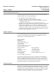
Installation and Operation Manual X-TMF-5800S-MFC-eng PN 541-C-051-AAG November, 2008 Models 5800-S Appendix B: Dimensional drawings Model 5860S 5860S CONNECTIONS 9/16-18 UNF (no adapters) 3/8" TUBE COMPR. 1/4" TUBE COMPR. 1/8" TUBE COMPR. 1/4" VCR 1/4" VCO 1/4" NPT 6mm TUBE COMPR. 10mm TUBE COMPR. 1/4" BSP A (mm) 59 113 110 105 106 98 99 110 113 99 Model 5861S Inches 2,31 4,45 4,33 4,15 4,19 3,87 3,89 4,33 4,45 3,89 Model 5863S 5863S CONNECTIONS 1/2" TUBE COMPR. 3/4" TUBE COMPR. 1" TUBE COMPR.
Installation and Operation Manual Appendix B X-TMF-5800S-MFC-eng PN 541-C-051-AAG November, 2008 Models 5800-S Model 5850S 5850S CONNECTIONS 9/16-18 UNF (no adapters) 3/8" TUBE COMPR. 1/4" TUBE COMPR. 1/8" TUBE COMPR. 1/4" VCR 1/4" VCO 1/4" NPT 6mm TUBE COMPR. 10mm TUBE COMPR. 1/4" BSP A (mm) 76 131 128 123 124 116 116 128 131 116 Model 5851S Inches 3 5,14 5,02 4,84 4,88 4,56 4,58 5,02 5,14 4,58 Model 5853S 5853S CONNECTIONS 1/2" TUBE COMPR. 3/4" TUBE COMPR. 1" TUBE COMPR.
Installation and Operation Manual Models 5800-S X-TMF-5800S-MFC-eng PN 541-C-051-AAG November, 2008 Appendix C: Translation of CE Marking electrical installation instructions Dansk Brooks Instrument har gennemført CE mærkning af elektronisk udstyr med succes, i henhold til regulativet om elektrisk støj (EMC direktivet 89/336/EEC). Der skal dog gøres opmærksom på benyttelsen af signalkabler i forbindelse med CE mærkede udstyr.
Installation and Operation Manual X-TMF-5800S-MFC-eng PN 541-C-051-AAG November, 2008 Appendix C Models 5800-S Español Los equipos de Brooks (eléctricos/electrónicos) en relación con la marca CE han pasado satisfactoriamente las pruebas referentes a las regulaciones de Compatibilidad Electro magnetica (EMC directiva 89/336/EEC).
Appendix C Models 5800-S Installation and Operation Manual X-TMF-5800S-MFC-eng PN 541-C-051-AAG November, 2008 Greek Italiano Questa strumentazione (elettrica ed elettronica) prodotta da Brooks Instrument, soggetta a marcatura CE, ha superato con successo le prove richieste dalla direttiva per la Compatibilità Elettomagnetica (Direttiva EMC 89/336/EEC). E’ richiesta comunque una speciale attenzione nella scelta dei cavi di segnale da usarsi con la strumentazione soggetta a marchio CE.
Installation and Operation Manual X-TMF-5800S-MFC-eng PN 541-C-051-AAG November, 2008 Appendix C Models 5800-S Nederlands Alle CE gemarkeerde elektrische en elektronische produkten van Brooks Instrument zijn met succes getest en voldoen aan de wetgeving voor Electro Magnetische Compatibiliteit (EMC wetgeving volgens 89/336/EEC). Speciale aandacht is echter vereist wanneer de signaalkabel gekozen wordt voor gebruik met CE gemarkeerde produkten.
Appendix C Installation and Operation Manual Models 5800-S X-TMF-5800S-MFC-eng PN 541-C-051-AAG November, 2008 Suomi Brooksin CE merkillä varustetut sähköiset laitteet ovat läpäissyt EMC testit (direktiivi 89/336/EEC). Erityistä huomiota on kuitenkin kiinnitettävä signaalikaapelin valintaan. Signaalikaapelin, kaapelin läpiviennin ja liittimen laatu Brooks toimittaa korkealaatuisia kaapeleita, jotka täyttävät CE sertifikaatin vaatimukset.
Installation and Operation Manual X-TMF-5800S-MFC-eng PN 541-C-051-AAG November, 2008 Models 5800-S Appendix D: Important Safety Instructions ENGLISH IMPORTANT SAFETY INSTRUCTIONS This appendix contains important safety and operating instructions for use with the Thermal Mass Flow Meter / Controller Series. The instrument complies to the (PED) PRESSURE EQUIPMENT CE DIRECTIVE 97/23/EC. Consult local authorities as to national and/or local safety codes and any additional installation requirements.
Installation and Operation Manual Appendix D X-TMF-5800S-MFC-eng PN 541-C-051-AAG November, 2008 Models 5800-S NEDERLANDS BELANGRIJKE VEILIGHEIDSINSTRUCTIES Deze appendix bevat belangrijke veiligheidsinstructies voor het gebruik van de Themal Mass Flow Meter/ Controller Series Deze instrumenten voldoen aan de (PED) Pressure Equipment CE Directive 97/23/EC (wet op het vervaardigen en distibueren van drukvaten binnen de Europese lidstaten).
Installation and Operation Manual X-TMF-5800S-MFC-eng PN 541-C-051-AAG November, 2008 Appendix D Models 5800-S DEUTSCH WICHTIGE SICHERHEITSHINWEISE Dieser Anhang enthält wichtige Hinweise für einen sicheren Betrieb des Ganzmetall-Schwebekörperdurchflussmessers der Baureihe Thermal Mass Flow Meter / Controller Series von Brooks Instrument . Das Gerät entspricht den gültigen PEDRichtlinien (PRESSURE EQUIPMENT CE DIRECTIVE 97/23/EC).
Installation and Operation Manual Appendix D X-TMF-5800S-MFC-eng PN 541-C-051-AAG November, 2008 Models 5800-S NORSK VIKTIG SIKKERHETS INSTRUKS Dette tillegget inneholder viktige sikkerhets og drifts instruksjoner for bruk av Brooks metall rør mengde måler Thermal Mass Flow Meter / Controller Series. Instrumentet tilfredstiller (PED) PRESSURE EQUIPMENT CE DIRECTIVE 97/23/EC. Kontakt lokale myndigheter for nasjonale eller lokale sikkerhetskoder og andre installasjonskrav. SIKKERHETS INSTRUKS 1. 2. 3. 4.
Installation and Operation Manual X-TMF-5800S-MFC-eng PN 541-C-051-AAG November, 2008 Appendix D Models 5800-S SWEDISH VIKTIG SÄKERHETSINFORMATION Denna bilaga innehåller viktig information om säkerhet och handhavande vid installation och användande av Brooks Flödesmätare i Thermal Mass Flow Meter / Controller Series. Instrumentet är i överensstämmande med (PED) PRESSURE EQUIPMENT CE DIRECTIVE 97/23/EC.
Installation and Operation Manual X-TMF-5800S-MFC-eng PN 541-C-051-AAG November, 2008 Models 5800-S Appendix E: Modellist BROOKS SMART MASS FLOW PRODUCTS SMART MASS FLOW METERS / CONTROLLERS 44 BASE M ODEL NUM BER DESCRIPTION 5860S/BA MA SS FLOW METER; F.S. FLOWRA NGES: 0.003 - 0.008 ln/min. 5860S/BC MA SS FLOW METER; F.S. FLOWRA NGES: 0.008 - 30 ln/min. 5861S/BD MA SS FLOW METER; F.S. FLOWRA NGES: 20 - 100 ln/min. 5863S/BE MA SS FLOW METER; F.S. FLOWRA NGES: 100 - 200 ln/min.
Installation and Operation Manual Appendix E X-TMF-5800S-MFC-eng PN 541-C-051-AAG November, 2008 Models 5800-S M ECHANICAL CONNECTIONS 1A WITHOUT A DA PTORS (9/16"-18" UNF) 1B 1/4" TUBE COMPRESSION FITTINGS (ONLY FOR 5850/60/51/61/53/63) (ONLY FOR 5850/60/51/61) 1C 1/8" TUBE COMPRESSION FITTINGS (ONLY FOR 5850/60/51/61) 1D 3/8" TUBE COMPRESSION FITTINGS (ONLY FOR 5851/61) 1E 1/4" V CR (ONLY FOR 5850/60/51/61) 1F 1/4" V CO (ONLY FOR 5850/60/51/61) 1G 1/4" NPT (ONLY FOR 5850/60/51
Installation and Operation Manual Appendix E X-TMF-5800S-MFC-eng PN 541-C-051-AAG November, 2008 Models 5800-S V ALV E TYPE 0 METER ONLY (NO V A LV E) 1 NORMA LLY CLOSED (5850/51 SERIES) 2 NORMA LLY CLOSED (PRESS.DIFF. >2BA R. 5853 SERIES) 3 NORMA LLY CLOSED (PRESS.DIFF. <2BA R. 5853 SERIES) 4 NORMA LLY OPENED 5 NORMA LLY CLOSED, 5850 SERIES, 300 BA R 9 SPECIFY (5850 ONLY ) ELECTRICAL INPUT/OUTPUT INPUT OUTPUT A 0-5V dc 0-5 V dc & 0-20mA (INCL.
Installation and Operation Manual Appendix E X-TMF-5800S-MFC-eng PN 541-C-051-AAG November, 2008 Models 5800-S ENHANCEM ENTS A STA NDA RD RESPONSE:< 1 SEC (5850/51) < 3 SEC (5853) [1]. B FA ST RESPONSE (SPECIFY V A LUES .... SEC.) [1] C LINEA R RA MP D FLOW OUTPUT DA MPING (SPECIFY V A LUES .... SEC.) [1] (SPECIFY V A LUES ....%/SEC.) [1] CALIBRATION 0 UNCA LIBRA TED 1 STA NDA RD CA LIBRA TION INCLUDED 2 STORA GE OF MULTIPLE CA L.
Appendix E Installation and Operation Manual X-TMF-5800S-MFC-eng PN 541-C-051-AAG November, 2008 Models 5800-S 3. OPTIONS A) HIGH PRESSURE RATING 300 BAR FOR MODEL 5861S B) FOR GASES WHICH CLOG AND CONTAMINATE THE MFC EASILY, AN ANTI-CLOG LAMINAR FLOW ELEMENT MUST BE ORDERED. FOR FLOW RANGES UP TO 3460 mln/min.
Installation and Operation Manual X-TMF-5800S-MFC-eng PN 541-C-051-AAG November, 2008 Models 5800-S THIS PAGE WAS INTENTIONALLY LEFT BLANK 49
Installation and Operation Manual X-TMF-5800S-MFC-eng PN 541-C-051-AAG November, 2008 Models 5800-S LIMITED WARRANTY Seller warrants that the Goods manufactured by Seller will be free from defects in materials or workmanship under normal use and service and that the Software will execute the programming instructions provided by Seller until the expiration of the earlier of twelve (12) months from the date of initial installation or eighteen (18) months from the date of shipment by Seller.