
User Manual


5-1
Installation and Operation Manual
X-VA-1110-1140-eng
Part Number: 541B040AAG
September, 2012 Brooks
®
1110 and 1140 Series
Section 5 Accessories
5-1 General
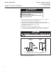
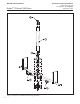
See Optional Equipment, Section 1-4, for specifications, dimensions, and
options. Refer to both parts of Figures 5-1a thru 5-1c and Table 5-1 for
exploded drawing and parts.
Table 5-1 Model 1110 Exploded Parts List
Component Applicable
to
Retro-Fi Kits
SEQ # PART DESCRIPTION Sz 2 & 6 Sz 7 - 10 Sz 12 & 13 Sz 7 Sz 8 Sz 9 Sz 10 Sz 12 Sz 13
1 Glass Tube X X X X X X X X X
2 Inlet Tube Packing X X X X X X X X X
3 Outlet Tube Packing X X X X X X X X X
4 Tube Seat Gasket X X X X X X X X X
5 Inlet Gland Ring X X X X X X X X X
6 Outlet Gland Ring X X X X X X X X X
7 Gland Followers X X X X X X
8Float X X X
9 Inlet Float Stop/Plug X X X
10 Inlet Spring Stop/Valve stop X X X
11 Outlet Float stop X X X
12 Outlet Spring Stop/Valve stop X X X
13 Inlet End Fitting X X X
14 Inlet Stuffing Box Ring X X X
15 Outlet End fitting X X X
16 O'Rings X X X
17 Right Scale Plate X X X
18 Scale X X X
19 Left Scale Plate X X X
20 Window Frame X X X
21 Window X X X X X X X X X
22 Window Gasket X X X X X X X X X
23 Warning Label X X X
24
V
alve Seat Assembly X X O
25 Tripod Base Plate
26 Panel Mounting Bracket
27 Inlet Tube Seat Insert X O O
28 Outlet Tube Seat Insert X O O
29 Warning Label (Side Plate)
30 Warning Label (Window)
31 Sleeve O X X X X X X X X
32 Bracket Cleat
33 Bracket Washe
r
34 Scale Mounting Screws X X X
35 Follower Screws X X X
36 Window Frame Screws X X X
37 Side Plate Screws X X X
38
V
alve Assembly X X O
X = Available O = Not Available