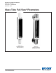
Installation and Operation Manual X-VA-1110-1140-eng Part Number: 541B040AAG September, 2012 Brooks® 1110 and 1140 Series 5 Glass Tube Full-View® Flowmeters Model 1110 Full-View Flowmeter (NPT Connections) Model 1140 Full-View Flowmeter (Flange Connections)
Brooks® 1110 and 1140 Series Installation and Operation Manual X-VA-1110-1140-eng Part Number: 541B040AAG September, 2012
Installation and Operation Manual X-VA-1110-1140-eng Part Number: 541B040AAG September, 2012 WARNING Brooks® 1110 and 1140 Series WARNING GLASS TUBE EXPLOSION HAZARD GLASS TUBE EXPLOSION HAZARD Plastic protective sleeve must remain over glass tube. (Meter sizes 7 -13 only) Fasten meter windows securely. Do not operate above pressure and temperature limits. Avoid pressure and flow surges. Do not service or repair while pressurized. Read and understand instruction manual.
Brooks® 1110 and 1140 Series Installation and Operation Manual X-VA-1110-1140-eng Part Number: 541B040AAG September, 2012 Dear Customer, We appreciate this opportunity to service your flow measurement and control requirements with a Brooks Instrument device. Every day, flow customers all over the world turn to Brooks Instrument for solutions to their gas and liquid low-flow applications.
Installation and Operation Manual X-VA-1110-1140-eng Part Number: 541B040AAG September, 2012 Paragraph Number Contents Brooks® 1110 and 1140 Series Page Number Section 1 Introduction 1-1 Description ......................................................................................................................................... 1-1 1-2 Design Features .................................................................................................................................
Contents Brooks® 1110 and 1140 Series Installation and Operation Manual X-VA-1110-1140-eng Part Number: 541B040AAG September, 2012 Figures Figure Page Number Number 1-1 Dimensions 127mm & 250mm Full-View Flowmeters ........................................................................ 1-6 1-3 Float Types ......................................................................................................................................... 1-7 2-1 Typical Bypass Installation ...........................
Section 1 Introduction Installation and Operation Manual X-VA-1110-1140-eng Part Number: 541B040AAG September, 2012 Brooks® 1110 and 1140 Series 1-1 Description The Brooks® Full-View® glass tube meters are designed to offer a wide variety of meter configurations to meet a broad range of metering applications. The packing gland seal construction provides for long-term, leak-free, and reliable flow measurement.
Section 1 Introduction Brooks® 1110 and 1140 Series Installation and Operation Manual X-VA-1110-1140-eng Part Number: 541B040AAG September, 2012 Pressure Ratings Refer to Table 1-1 for maximum non-shock pressure for rib guided and plain tapered tubes. Note: CRN meters have a lower pressure rating. Pressure Equipment Directive (PED) 97/23/EC See Table 1-1. Scales Standard: Detachable aluminum plate. Length: 127mm, 150mm and 250mm.
Section 1 Introduction Installation and Operation Manual X-VA-1110-1140-eng Part Number: 541B040AAG September, 2012 Brooks® 1110 and 1140 Series WARNING GLASS TUBE EXPLOSION HAZARD Plastic protective sleeve must remain over glass tube. (Meter sizes 7 -13 only) Fasten meter windows securely. Do not operate above pressure and temperature limits. Avoid pressure and flow surges. Do not service or repair while pressurized. Read and understand instruction manual.
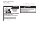
Section 1 Introduction Installation and Operation Manual X-VA-1110-1140-eng Part Number: 541B040AAG September, 2012 Brooks® 1110 and 1140 Series Housing and Window Bezel Standard: Aluminum with polyurethane paint. Optional: 18-8 stainless steel. End Fittings 316 stainless steel,steel, Hastelloy C, CPVC Sizes 2-8, PVC Sizes 9-10, brass. (Brass, Hastelloy C, CPVC/PVC fittings not available with flanged connection). Window Scratch resistant, UV stabilized polycarbonate.
Section 1 Introduction Installation and Operation Manual X-VA-1110-1140-eng Part Number: 541B040AAG September, 2012 Brooks® 1110 and 1140 Series Table 1-2 Connections Meter Size Model 1110 Inlet&Outlet Horizontal (NPT) Model 1114 Inlet&Outlet Vertical (NPT) Model 1140 Inlet&Outlet Horizontal (Flange) Model 1144 Inlet&Outlet Vertical (Flange) 2 to 6 7 and 8 9 10 12 13 1/4" 1/2" 3/4" 3/4" 1-1/2" 1-1/2" 1/4" 1/2" 3/4" 1" 1-1/2" 2" 1/2" 1/2" 1" 1" 1-1/2" 2" 1/2" 1/2" 1" 1" 1-1/2" 2" 1-5
Section 1 Introduction Brooks® 1110 and 1140 Series Installation and Operation Manual X-VA-1110-1140-eng Part Number: 541B040AAG September, 2012 All Dimensions in Inches 1110 - 1140 1114 1144 Nominal Nominal All All Meter Nominal Scale Length (MM) Scale Length Scale Length Meters Meters (MM) (MM) Size 127 250 127 250 127 250 A B A B A A A A D E 2-6* 10.12 8.59 15.12 13.59 9.63 14.63 14.88 19.88 2.38 3.5 7&8 15.38 11.5 20.38 16.5 12 17 17.88 22.88 3.25 3.5 9 17 12.5 22 17.5 12.25 17.25 17.75 22.75 3.
Section 1 Introduction Installation and Operation Manual X-VA-1110-1140-eng Part Number: 541B040AAG September, 2012 Brooks® 1110 and 1140 Series 1-4 Optional Equipment ( Mountings, Valves and Flow Controllers) • Mountings: Brackets for panel mounting flush or front of panel • Valves: Available for connection sizes 1/4” through 1” only. Horizontal stem in outlet or inlet and fitting Sizes 2 through 10. • Flow Controller: Brass or 316 Stainless steel integrally piped to Sizes 2-6.
Section 1 Introduction Installation and Operation Manual X-VA-1110-1140-eng Part Number: 541B040AAG September, 2012 Brooks® 1110 and 1140 Series Table 1-3 Capacities, 150mm Scale, Rib Guided Tube, Spherical Float METER SIZE 2 6 TUBE FLOAT GLASS * SAPPHIRE R-2-15-AAAA STN. STL. SEE NOTE CARBOLOY BELOW * TANTALUM GLASS SAPPHIRE R-2-15-AA STN. STL. CARBOLOY TANTALUM GLASS SAPPHIRE R-2-15-D STN. STL. CARBOLOY TANTALUM GLASS SAPPHIRE R-2-15-A STN. STL. CARBOLOY TANTALUM GLASS SAPPHIRE R-2-15-B STN. STL.
Installation and Operation Manual X-VA-1110-1140-eng Part Number: 541B040AAG September, 2012 Section 1 Introduction Brooks® 1110 and 1140 Series Table 1-5 Capacities, 250mm Scale , Rib Guided Tubes, Standard Float Water Air @ 14.7 psia and 70°F (21°C) Pressure Viscosity Pressure Meter Drop Immunity Drop psi Size Tube Float gpm lpm Inches W.C. Ceiling, CS1 scfm slpm Inches W.C. Critical2 8-RV-3 0.55 2.08 2.0 2.0 2.22 62.9 3.0 0 8-RV-8 0.78 2.95 5.0 3.3 3.22 91.2 6.0 0 8-RS-8 1.00 3.79 6.0 1.7 4.18 118.
Section 1 Introduction Brooks® 1110 and 1140 Series Installation and Operation Manual X-VA-1110-1140-eng Part Number: 541B040AAG September, 2012 Table 1-6 Capacities, 127mm Scale, Rib Guided Tubes, Standard Float Water Air @ 14.7 psia and 70°F (21°C) Pressure Viscosity Pressure Meter Drop Immunity Drop psi Size Tube Float gpm lpm Inches W.C. Ceiling, CS1 scfm slpm Inches W.C. Critical2 8-RV-3 0.50 1.89 2.0 2.0 2.05 58.1 2.0 0 8-RV-8 0.74 2.80 3.0 3.3 3.01 85.2 4.0 0 8-RS-8 0.92 3.48 4.0 1.7 3.84 108.7 4.
Installation and Operation Manual X-VA-1110-1140-eng Part Number: 541B040AAG September, 2012 Section 2 Installation Brooks® 1110 and 1140 Series 2-1 General This section contains the procedures for the receipt and installation of the instrument. Do not attempt to start the system until the instrument has been permanently installed. It is extremely important that the start-up procedures be followed in the exact sequence presented.
Section 2 Installation Brooks® 1110 and 1140 Series Installation and Operation Manual X-VA-1110-1140-eng Part Number: 541B040AAG September, 2012 2-4 Return Shipment Prior to returning any instrument to the factory, contact your nearest Brooks location for a Return Materials Authorization Number (RMA#). This can be obtained from one of the following locations: Brooks Instrument 407 W. Vine Street P.O.
Section 2 Installation Installation and Operation Manual X-VA-1110-1140-eng Part Number: 541B040AAG September, 2012 Brooks® 1110 and 1140 Series 2-7 Installation of meter A. Location For proper operation of the Full-View flowmeter it must be mounted within 6 degrees of true vertical, with the inlet connection at the bottom of the meter, and the outlet at the top. The use of a level is recommended to assure vertical positioning. B.
Section 2 Installation Installation and Operation Manual X-VA-1110-1140-eng Part Number: 541B040AAG September, 2012 Brooks® 1110 and 1140 Series THIS PAGE WAS INTENTIONALLY LEFT BLANK 2-4
Installation and Operation Manual X-VA-1110-1140-eng Part Number: 541B040AAG September, 2012 Section 3 Operation Brooks® 1110 and 1140 Series 3-1 General After the flowmeter has been properly installed in the process, it is ready for operation. When initiating flow, slowly open the valve to avoid a flow surge.Bypass is a help in bringing the flow on smoothly. Avoid starting a pump to supply the flowmeter without the use of a valve upstream of the flowmeter.
Installation and Operation Manual X-VA-1110-1140-eng Part Number: 541B040AAG September, 2012 Section 3 Operation Brooks® 1110 and 1140 Series WARNING GLASS TUBE EXPLOSION HAZARD Protective sleeve must remain over glass tube. (Meter sizes 7 - 13 only) Fasten meter windows securely. Failure to comply could result in serious personal injury or property damage. To initiate flow through a flowmeter using bypass piping, refer to Figure 3-1. 1. Close flowmeter isolation valves (A) and (B). 2.
Installation and Operation Manual X-VA-1110-1140-eng Part Number: 541B040AAG September, 2012 Section 4 Maintenance and Cleaning Brooks® 1110 and 1140 Series 4-1 General This section provides the assembly and disassembly procedures for the Brooks Full-View flowmeters.
Section 4 Maintenance and Cleaning Brooks® 1110 and 1140 Series Installation and Operation Manual X-VA-1110-1140-eng Part Number: 541B040AAG September, 2012 4-2 Disassembly and Reassembly Note: Step number preceded by an asterisk (*) apply only to rod guided floats. A. Disassembly 1. Remove the four bolts attaching each window frame. Carefully remove both windows and frames. 2. Loosen, but do not remove, the four gland bolts in each end fitting. 3. Remove the four bolts attaching each side plate.
Installation and Operation Manual X-VA-1110-1140-eng Part Number: 541B040AAG September, 2012 Section 4 Maintenance and Cleaning Brooks® 1110 and 1140 Series 4. Install the gland followers, polycarbonate sleeve, Size 7 (1/2") and larger, gland rings, and packing on the tube. Note: Both hat gaskets are purposely tight fitting and can be installed more easily from the inlet (narrower) end of the tube. The inlet (smaller) gasket is often difficult to place over the glass tube.
Section 4 Maintenance and Cleaning Brooks® 1110 and 1140 Series THIS PAGE WAS INTENTIONALLY LEFT BLANK 4-4 Installation and Operation Manual X-VA-1110-1140-eng Part Number: 541B040AAG September, 2012
Section 5 Accessories Installation and Operation Manual X-VA-1110-1140-eng Part Number: 541B040AAG September, 2012 Brooks® 1110 and 1140 Series 5-1 General See Optional Equipment, Section 1-4, for specifications, dimensions, and options. Refer to both parts of Figures 5-1a thru 5-1c and Table 5-1 for exploded drawing and parts.
Section 5 Accessories Brooks® 1110 and 1140 Series Figure 5-1a Model 1110 Exploded Parts Drawing 5-2 Installation and Operation Manual X-VA-1110-1140-eng Part Number: 541B040AAG September, 2012
Installation and Operation Manual X-VA-1110-1140-eng Part Number: 541B040AAG September, 2012 Section 5 Accessories Brooks® 1110 and 1140 Series Figure 5-1b Model 1110 Exploded Parts Drawing (Continued) 5-3
Section 5 Accessories Brooks® 1110 and 1140 Series Figure 5-1c Model 1110 Exploded Parts Drawing (Continued) 5-4 Installation and Operation Manual X-VA-1110-1140-eng Part Number: 541B040AAG September, 2012
Installation and Operation Manual Section A - Essential Instructions X-VA-1110-1140-eng Part Number:541B040AAG September, 2012 Brooks® 1110 and 1140 Series Bulgarian Ɉɫɧɨɜɧɢ ɢɧɫɬɪɭɤɰɢɢ ɉɪɨɱɟɬɟɬɟ ɩɪɟɞɢ ɪɚɛɨɬɚ! Brooks Instrument ɩɪɨɟɤɬɢɪɚ, ɩɪɨɢɡɜɟɠɞɚ ɢ ɬɟɫɬɜɚ ɩɪɨɞɭɤɬɢɬɟ ɫɢ ɩɨ ɬɚɤɴɜ ɧɚɱɢɧ, ɱɟ ɬɟ ɞɚ ɨɬɝɨɜɚɪɹɬ ɧɚ ɦɧɨɝɨɛɪɨɣɧɢ ɧɚɰɢɨɧɚɥɧɢ ɢ ɦɟɠɞɭɧɚɪɨɞɧɢ ɫɬɚɧɞɚɪɬɢ.
Section A - Essential Instructions Installation and Operation Manual Brooks® 1110 and 1140 Series X-VA-1110-1140-eng Part Number:541B040AAG September, 2012 Czech Základní instrukce PĜed instalací si pĜeþtČte následující instrukce! Spoleþnost Brooks Instrument konstruuje, vyrábí a testuje tento produkt tak, aby splnil mnoho národních a mezinárodních standardĤ.
Installation and Operation Manual Section A - Essential Instructions X-VA-1110-1140-eng Part Number:541B040AAG September, 2012 Brooks® 1110 and 1140 Series Dansk Grundlæggende vejledninger Læs disse før anvendelse! Brooks Instruments designer, fremstiller og afprøver sine produkter således, at de tilpasser sig både de indenrigs og internationale standarder. Disse udstyr bør installeres, bruges og repareres omhyggeligt, så at de kan virke tilsvarende deres normale anvendelsesperiode.
Section A - Essential Instructions Installation and Operation Manual Brooks® 1110 and 1140 Series X-VA-1110-1140-eng Part Number:541B040AAG September, 2012 Dutch Essentiële instructies Lees ze voordat u verder gaat! Brooks Instrument ontwerpt, produceert en test haar producten zodanig dat ze voldoen aan vele nationale en internationale normen. Deze producten moeten correct worden geïnstalleerd, bediend en onderhouden zodat ze binnen hun normale specificaties blijven werken.
Installation and Operation Manual Section A - Essential Instructions X-VA-1110-1140-eng Part Number:541B040AAG September, 2012 Brooks® 1110 and 1140 Series Estonian Olulised juhised Enne kasutamist lugege hoolikalt läbi! Brooks Instrument konstrueerib, valmistab ja katsetab oma tooteid selliselt, et need vastaksid paljude erinevate riiklike ja rahvusvaheliste standardite nõuetele. Ainult nõuetekohane paigaldamine, kasutamine ja hooldamine tagab toodete katkematu talitluse tavaspetsifikatsiooni raames.
Section A - Essential Instructions Installation and Operation Manual Brooks® 1110 and 1140 Series X-VA-1110-1140-eng Part Number:541B040AAG September, 2012 Finnish Perusohjeet Lue ensin ohjeet huolellisesti! Brooks Instrument suunnittelee, valmistaa ja testaa laitteensa vastaamaan useimpien kotimaisten ja kansainvälisten standardien vaatimuksia. Tuotteet tulee asentaa, käyttää ja huoltaa käyttöohjeiden mukaan jotta niiden toimivuus taataan.
Installation and Operation Manual Section A - Essential Instructions X-VA-1110-1140-eng Part Number:541B040AAG September, 2012 Brooks® 1110 and 1140 Series French Instructions essentielles A lire avant de commencer ! Brooks Instrument conçoit, fabrique et teste ses produits pour répondre à de nombreuses normes nationales et internationales. Ces produits doivent être correctement installés, utilisés et entretenus pour pouvoir fonctionner dans le cadre de leurs spécifications normales.
Section A - Essential Instructions Installation and Operation Manual Brooks® 1110 and 1140 Series X-VA-1110-1140-eng Part Number:541B040AAG September, 2012 German Wichtige Anweisungen Bitte zuerst lesen! Brooks Instrument entwickelt, produziert und testet seine Produkte derart, dass sie viele nationale und internationale Standards erfüllen. Nur bei korrektem Einbau sowie richtiger Bedienung und Wartung dieser Produkte ist ein Betrieb unter Einhaltung der Standardvorgaben sichergestellt.
Installation and Operation Manual Section A - Essential Instructions X-VA-1110-1140-eng Part Number:541B040AAG September, 2012 Brooks® 1110 and 1140 Series Greek ǺĮıȚțȑȢ ȠįȘȖȓİȢ ǻȚĮȕȐıIJİ ʌȡȚȞ ıȣȞİȤȓıİIJİ! Ǿ Brooks Instrument ıȤİįȚȐȗİȚ, ʌĮȡȐȖİȚ țĮȚ įȠțȚȝȐȗİȚ IJĮ ʌȡȠȧȩȞIJĮ IJȘȢ ıİ ıȣȝȝȩȡijȦıȘ ȝİ ʌȜȒșȠȢ İșȞȚțȫȞ țĮȚ įȚİșȞȫȞ ʌȡȠIJȪʌȦȞ. Ǿ ıȦıIJȒ İȖțĮIJȐıIJĮıȘ, ȤȡȒıȘ țĮȚ ıȣȞIJȒȡȘıȒ IJȠȣȢ ĮʌȠIJİȜİȓ ĮʌĮȡĮȓIJȘIJȘ ʌȡȠȨʌȩșİıȘ IJȘȢ ȜİȚIJȠȣȡȖȓĮȢ İȞIJȩȢ IJȦȞ țĮȞȠȞȚțȫȞ ȠȡȓȦȞ.
Section A - Essential Instructions Installation and Operation Manual Brooks® 1110 and 1140 Series X-VA-1110-1140-eng Part Number:541B040AAG September, 2012 Hungarian AlapvetĘ utasítások ElĘször olvassa el ezeket! A Brooks Instrument olyan módon tervezi, gyártja és teszteli termékeit, hogy azok megfeleljenek számos belföldi és nemzetközi szabványnak.
Installation and Operation Manual Section A - Essential Instructions X-VA-1110-1140-eng Part Number:541B040AAG September, 2012 Brooks® 1110 and 1140 Series Italian Istruzioni fondamentali Leggerle subito! La Brooks Instrument progetta, fabbrica e collauda i propri prodotti in maniera tale che siano conformi ai vari standard nazionali ed internazionali.
Section A - Essential Instructions Installation and Operation Manual Brooks® 1110 and 1140 Series X-VA-1110-1140-eng Part Number:541B040AAG September, 2012 Latvian SvarƯga instrukcija Pirms turpinƗt izlasiet! „Brooks Instrument” projektƝ, ražo un pƗrbauda savus ražojumus atbilstoši daudziem nacionƗlajiem un starptautiskajiem standartiem. Lai nodrošinƗtu šo izstrƗdƗjumu turpmƗku darbƯbu atbilstoši noteiktajiem parametriem, tie ir pareizi jƗuzstƗda, jƗlieto un jƗapkopj.
Installation and Operation Manual Section A - Essential Instructions X-VA-1110-1140-eng Part Number:541B040AAG September, 2012 Brooks® 1110 and 1140 Series Lithuanian Pagrindinơs instrukcijos Perskaitykite prieš tĊsdami! „Brooks Instrument“ projektuoja, gamina ir išbando savo gaminius, kad jie atitiktǐ Ƴvairius nacionalinius ir tarptautinius standartus. Šie gaminiai turi bnjti tinkamai montuojami, eksploatuojami ir prižinjrimi, kad ir toliau veiktǐ pagal jiems bnjdingus techninius parametrus.
Section A - Essential Instructions Installation and Operation Manual Brooks® 1110 and 1140 Series X-VA-1110-1140-eng Part Number:541B040AAG September, 2012 Polish Zalecenia wstĊpne Prosimy przeczytaü przed rozpoczĊciem uĪytkowania! Brooks Instrument projektuje, wytwarza i testuje swoje produkty tak, aby speániaáy wymagania licznych norm krajowych i miĊdzynarodowych.
Installation and Operation Manual Section A - Essential Instructions X-VA-1110-1140-eng Part Number:541B040AAG September, 2012 Brooks® 1110 and 1140 Series Portuguese Instruções Básicas Ler antes de proceder! A Brooks Instrument projecta, fabrica e testa os seus produtos de forma a satisfazer numerosas normas nacionais e internacionais. Estes equipamentos devem ser instalados, utilizados e mantidos de forma adequada, e devem funcionar dentro da sua gama de utilização.
Section A - Essential Instructions Installation and Operation Manual Brooks® 1110 and 1140 Series X-VA-1110-1140-eng Part Number:541B040AAG September, 2012 Romanian IndicaĠii de referinĠă CitiĠi-le întâi pe acestea! Brooks Instrument îúi proiectează, produce úi testează produsele într-un mod ce respectă un mare număr de standarde autohtone úi internaĠionale.
Installation and Operation Manual Section A - Essential Instructions X-VA-1110-1140-eng Part Number:541B040AAG September, 2012 Brooks® 1110 and 1140 Series Slovak Základné príkazy PreþítaĢ pred inštaláciou! Brooks Instrument svoje výrobky projektuje, vyrába a testuje takým spôsobom, aby tieto vyhoveli domácim aj medzinárodným normám. Tieto zariadenia je potrebné predpísaným spôsobom inštalovaĢ, prevádzkovaĢ a udržiavaĢ, na zabezpeþenie ich spoĐahlivej a normálnej prevádzky v celom pracovnom rozsahu.
Section A - Essential Instructions Installation and Operation Manual Brooks® 1110 and 1140 Series X-VA-1110-1140-eng Part Number:541B040AAG September, 2012 Slovene Osnovna navodila Najprej preberite jih Brooks Instrument tako konstruira, izdeluje in terstira svoje izdelke, da oni ustrezajo številnim domaþim in mednarodnim standardom. Te naprave se morajo ustrezno instalirati, koristiti in vzdrževati, da vsekakor delajo ustrezno normalnom podroþju funkcioniranja.
Installation and Operation Manual Section A - Essential Instructions X-VA-1110-1140-eng Part Number:541B040AAG September, 2012 Brooks® 1110 and 1140 Series Spanish Instrucciones básicas ¡Léalos primero! El Brooks Instrument proyecta, fabrica y prueba sus productos de manera que éstos respondan a numerosas normas nacionales e internacionales.
Section A - Essential Instructions Installation and Operation Manual Brooks® 1110 and 1140 Series X-VA-1110-1140-eng Part Number:541B040AAG September, 2012 Swedish Väsentliga anvisningar. Läs detta innan du fortsätter ! Brooks Instrument konstruerar, tillverkar och testar sina produkter med syfte att uppfylla alla nationella och internationella standarder. Dessa produkter måste installeras på rätt sätt, handhas och underhållas för att de skall fungera kontinuerligt enligt deras normala specifikation.
Installation and Operation Manual X-VA-1110-1140-eng Part Number: 541B040AAG September, 2012 Brooks® 1110 and 1140 Series THIS PAGE WAS INTENTIONALLY LEFT BLANK
Brooks® 1110 and 1140 Series Installation and Operation Manual X-VA-1110-1140-eng Part Number: 541B040AAG September, 2012 LIMITED WARRANTY Seller warrants that the Goods manufactured by Seller will be free from defects in materials or workmanship under normal use and service and that the Software will execute the programming instructions provided by Seller until the expiration of the earlier of twelve (12) months from the date of initial installation or eighteen (18) months from the date of shipment by Se