Installation Guide
Manuals
Brands
Brooks Automation Manuals
Electronics
RFID UHF Reader
21
22
23
24
25
26
27
28
29
30
Table Of Contents
Installation Guide RFID Reader UF70 Certum
1 Identification
2 Safety Instructions
2.1 Area of application and symbols
2.1.1 Safety symbols - in compliance with 4844-2
2.1.2 Warning symbols
2.1.3 Prohibition symbols
2.1.4 Other symbols
2.2 ESD instructions
2.3 Residual risks
2.4 Additional instructions
3 Product Specifications
3.1 Images
3.1.1 Front view
3.1.2 Rear view
3.1.3 Top view
3.2 Description of the components
3.3 Technical data
3.3.1 Device label
4 Installation
4.1 Safety instructions
4.2 Qualified installation personnel
4.3 Unpacking
4.4 Assembly of the device
4.5 Antenna installation
4.6 Power supply
4.7 Terminal connection
4.8 External input and output (optional)
4.9 Commissioning
4.9.1 Required operating conditions
4.9.2 Parameters of the serial interface
4.9.3 Parameters of the Ethernet interface
5 Service and Troubleshooting
5.1 Customer service
5.2 Troubleshooting
6 Dismantling and Disposal
6.1 Dismantling
6.2 Disposal
Index
Chapter 4
Installation
Installation Guide - RFID Reader UF70 Certum
25
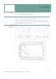
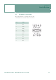
4.7
Terminal connection
The serial interface is a Sub-D socket (9-pin).
A normal RS232 extension cable can be used.
Pin
DB9
1
NC
2
TxD
3
RxD
4
NC
5
GND
6
NC
7
NC
8
NC
9
NC
1
...
...
23
24
25
26
27
...
...
33