
User's Manual

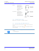


Table Of Contents
- 1 Identification
- 2 Declaration of Conformity
- 3 General Instructions
- 4 Safety Instructions
- 5 Product Specifications
- 6 Installation
- 7 Operation
- 7.1 Operating Personnel
- 7.2 Theory of Operation
- 7.3 Data Items Dictionary
- 7.4 Attribute (ECID and SVID) Values
- AlarmStatus (Read only)
- ASCII_T1 (ASCII only)
- ASCII_T3 (ASCII only)
- BAUDRATE
- CarrierIDLength
- CarrierIDOffset
- CHECKSUM (ASCII only)
- CID_DISPLAY
- CID_E99_PAD
- CID_ERROR
- CID_JUSTIFY
- CID_MAX_LENGTH
- CID_NP_ASCII
- CID_PAD
- Configuration (Read only)
- DeviceID
- DeviceType (Read only)
- DUAL_SENSOR
- ENABLE_EVENTS
- ENABLE_TIMEOUTS (ASCII only)
- EXTENDEDSSACK
- HardwareRevision- Level
- HeadID
- HeadStatus
- HOST_CONT_PORT1 _LED
- HOSTNAME
- MANTWRITEONLY
- Manufacturer
- MDLN
- ModelNumber
- OperationalStatus
- PARITY
- PIP (Read only)
- PIP_AUTOREAD
- PIP_AUTOREAD_ DATA
- PIP_AUTOREAD_ LENGTH
- PIP_SENSOR_ POLARITY
- RADIO_RETRY
- RDA
- RW_ADJUSTMENT
- RW_REPEATTIME
- SELF_TEST_ RESULT
- SENSOR_TIMEOUT
- SERIALNUM
- SerialNumber
- SIGNALSTRENGTH (Read only)
- SW_PARTNUMBER
- SOFTREV
- SoftwareRevision- Level
- STATUS_ENABLE
- TARGETID
- USETESTDIP
- 7.5 Operation of the SECS Protocol
- 8 Service and Troubleshooting
- 9 Dismantling and Storage
- 10 Transport and Disposal

Brooks Automation
34 260301 Revision A
6 Installation ATR60LF RFID Reader CAN Bus
6.11 DIP Switches Product Manual
6.11 DIP Switches
The DIP switches 1 to 5 set the TargetID (0 - 31). The TargetID of the CAN
Gateway has value 0. The new TargetID is set when the reader is powered.
Switch 1 is the LSB and switch 5 is the MSB of the TargetID. A switch at ON
or Open position is 1, a switch at OFF or Close is 0.
Switch position
values:
01 - 00001
03 - 00011
10 - 01010
16 - 10000
27 - 11011
31 - 11111
Switch # 1 2 3 4 5
Binary digit 1 2 4 8 16
Switch # Function
6 Switches between reading and writing action in test
mode.
OFF - only reading a transponder
ON - reading and writing a transponder
7 Switches the reader into test mode.
In test mode, the reader reads or writes (depends on
the setting of switch 6) permanently to the transpon-
der, and shows the result via LED 'Read/Write ok' and
'Read/Write fail'.
"ON" test mode activation
8 The trigger in the ON position performs an antenna
tuning cycle.