
User's Manual

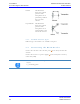


Table Of Contents
- 1 Identification
- 2 Declaration of Conformity
- 3 General Instructions
- 4 Safety Instructions
- 5 Product Specifications
- 6 Installation
- 7 Operation
- 7.1 Operating Personnel
- 7.2 Theory of Operation
- 7.3 Data Items Dictionary
- 7.4 Attribute (ECID and SVID) Values
- AlarmStatus (Read only)
- ASCII_T1 (ASCII only)
- ASCII_T3 (ASCII only)
- BAUDRATE
- CarrierIDLength
- CarrierIDOffset
- CHECKSUM (ASCII only)
- CID_DISPLAY
- CID_E99_PAD
- CID_ERROR
- CID_JUSTIFY
- CID_MAX_LENGTH
- CID_NP_ASCII
- CID_PAD
- Configuration (Read only)
- DeviceID
- DeviceType (Read only)
- DUAL_SENSOR
- ENABLE_EVENTS
- ENABLE_TIMEOUTS (ASCII only)
- EXTENDEDSSACK
- HardwareRevision- Level
- HeadID
- HeadStatus
- HOST_CONT_PORT1 _LED
- HOSTNAME
- MANTWRITEONLY
- Manufacturer
- MDLN
- ModelNumber
- OperationalStatus
- PARITY
- PIP (Read only)
- PIP_AUTOREAD
- PIP_AUTOREAD_ DATA
- PIP_AUTOREAD_ LENGTH
- PIP_SENSOR_ POLARITY
- RADIO_RETRY
- RDA
- RW_ADJUSTMENT
- RW_REPEATTIME
- SELF_TEST_ RESULT
- SENSOR_TIMEOUT
- SERIALNUM
- SerialNumber
- SIGNALSTRENGTH (Read only)
- SW_PARTNUMBER
- SOFTREV
- SoftwareRevision- Level
- STATUS_ENABLE
- TARGETID
- USETESTDIP
- 7.5 Operation of the SECS Protocol
- 8 Service and Troubleshooting
- 9 Dismantling and Storage
- 10 Transport and Disposal

Brooks Automation
260301 Revision A 31
ATR60LF RFID Reader CAN Bus 6 Installation
Product Manual 6.7 Power/CAN Bus Connection
6.7 Power/CAN Bus Connection
The device can be connected to an interior DC power circuit of the
equipment or to a DC adapter.
Once the device is connected to the power supply, the power LED lights up.
If the LED does not light up, please refer to chapter Customer Service.
6.8 RS232 Connection
The RS232 port is a shielded RJ45 socket. A cable for connecting to a PC is
available.
DANGER
Risk of death due to dangerous voltage
Risks exist when supplying the device with the incorrect voltage.
Only use cables, plugs and adapters supplied by Brooks.
Observe power ratings of the technical data ( Technical Data).
Pin Signal
1 Not used
2 CAN Low
3 Signal ground
4 Not used
5 Power ground
6 Signal ground
7 CAN High
8 Not used
9 +24 V DC
Pin Signal
4 Ground
5 TxD
6 RxD