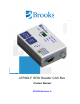
ATR60LF RFID Reader CAN Bus Product Manual 260301 Revision A
ATR60LF RFID Reader CAN Bus Product Manual ii Brooks Automation 260301 Revision A
ATR60LF RFID Reader CAN Bus Product Manual Brooks Automation Information provided within this document is subject to change without notice, and although believed to be accurate, Brooks Automation assumes no responsibility for any errors, omissions, or inaccuracies.
ATR60LF RFID Reader CAN Bus Product Manual Corporate Headquarters Fremont Office 15 Elizabeth Drive 46702 Bayside Parkway Chelmsford, MA 01824 U.S.A. Fremont, CA 94539 U.S.A For Technical Support: Location GUTS® Contact Number North America +1-800-FOR-GUTS (1-800-367-4887) +1-978-262-2900 Europe +49-1804-CALL-GUTS (+49-1804-2255-4887) Japan +81-45-477-5980 China +86-21-5131-7066 Taiwan +886-3-5525225 Korea +82-31-288-2500 Singapore +65-6464-1481 Visit us online: www.brooks.
ATR60LF RFID Reader CAN Bus Product Manual Brooks Automation, Inc. 46702 Bayside Parkway Fremont, CA 94538 Tel: +1 510-661-5000 Fax: +1 510-661-5166 Brooks Locations Worldwide: Brooks Automation Inc. 15 Elizabeth Drive Chelmsford, MA 01824-2400 Tel: +1-978-262-2400 Fax: +1-978-262-2500 www.brooks.com Brooks Life Science Systems 14100 Danielson Street, Bldg 100 Poway, CA 92064 Tel: +1 858-527-7000 Fax: +1 858-679-1255 Brooks Life Science Systems 1003 E Trent Street.
ATR60LF RFID Reader CAN Bus Product Manual vi Brooks Automation 260301 Revision A
ATR60LF RFID Reader CAN Bus Product Manual Revision History This section gives an overview of the change history for the document.
ATR60LF RFID Reader CAN Bus Product Manual viii Brooks Automation 260301 Revision A
ATR60LF RFID Reader CAN Bus Product Manual Table of Contents Revision History 1 2 Identification . . . . . . . . . . . . . . . . . . . . 1 1.1 Model 1 1.2 Designated Use 1 1.3 Incorrect Use 2 Declaration of Conformity . . . . . . . . . . . 3 2.1 2.2 3 4 5 Brooks Automation 260301 Revision A . . . . . . . . . . . . . . . . . vii USA - Federal Communications Commission (FCC) 3 Europe - CE Conformity 5 General Instructions . . . . . . . . . . . . . . 7 3.1 Liability and Warranty 7 3.
ATR60LF RFID Reader CAN Bus Product Manual 6 7 x 5.2.1 Front View 19 5.2.2 Rear View 20 5.2.3 Top View 21 5.3 Description of Components 22 5.4 Technical Data 23 5.4.1 Device Label 24 5.4.2 Power Supply and Current Input 24 Installation . . . . . . . . . . . . . . . . . . . . 25 6.1 Safety Instructions 25 6.2 Qualified Installation Personnel 27 6.3 Unpacking 27 6.4 Assembly of the Device 28 6.5 Antenna Installation 29 6.5.1 Positioning the Antenna 29 6.5.
ATR60LF RFID Reader CAN Bus Product Manual 8 9 10 Service and Troubleshooting . . . . . . . 81 8.1 General 81 8.2 Qualified Troubleshooting Personnel 82 8.3 Safety Instructions 82 8.4 Error Codes 83 8.4.1 SSACK 83 8.4.2 Stream Function 84 8.5 Error Display with LED 85 8.5.1 Power LED Does Not Light Up 85 8.5.2 Read Fail LED Flashes 85 8.6 Reader Does Not Respond 85 8.7 Reset 86 8.8 Power Cut 86 8.9 Software Releases 86 8.
ATR60LF RFID Reader CAN Bus Product Manual xii Brooks Automation 260301 Revision A
ATR60LF RFID Reader CAN Bus Product Manual 1 1 Identification 1.1 Model Identification This chapter gives you an overview of the following topics: Model Designated Use Incorrect Use 1.1 M odel ATR60LF READER CAN Bus Serial number Part number Manufacturer e.g. 1607SNI12345 TLS-33C-4O00-C1-00E2 Brooks Automation Inc. 46702 Bayside Parkway Fremont, CA 94538 Tel: +1 510-661-5000 Fax: +1 510-661-5166 Website www.brooks.com For information on the label, see Device Label. 1.
1 Identification 1.3 Incorrect Use ATR60LF RFID Reader CAN Bus Product Manual Intended use also includes the following: following all instructions in the operating instructions observing all safety information Before using the device, the user should ensure that the national approval requirements for use are met. 1.
ATR60LF RFID Reader CAN Bus Product Manual 2 2 Declaration of Conformity 2.1 USA - Federal Communications Commission (FCC) Declaration of Conformity This chapter gives you an overview of the following topics: USA - Federal Communications Commission (FCC) Europe - CE Conformity 2.1 U SA - Federal Communications Commission (FCC) This device complies with Part 15 of the FCC Rules. Operation is subject to the following two conditions: This device may not cause harmful interference.
2 Declaration of Conformity 2.1 USA - Federal Communications Commission (FCC) ATR60LF RFID Reader CAN Bus Product Manual FCC ID: N5GATR60LFCAN Compliance with: FCC Code of Federal Regulations, Part 15 Subpart C, Section §15.205 FCC Code of Federal Regulations, Part 15 Subpart C, Section §15.209 IMPORTANT 4 Changes or modifications not expressly approved by Brooks Automation, Inc. could void the user's authority to operate the equipment.
ATR60LF RFID Reader CAN Bus Product Manual 2.2 2 Declaration of Conformity 2.2 Europe - CE Conformity E ur ope - CE Co nfo rmity Declaration of Conformity For the European Union Description Function: Part Number: Document #: Rev.: A ATR60LF CAN Reader RFID Reader TLS-33C-XXXX-XX-XXXX Business name and full address of the manufacturer of the machinery: Brooks Automation Inc.
2 Declaration of Conformity 2.
ATR60LF RFID Reader CAN Bus Product Manual 3 3 General Instructions 3.1 Liability and Warranty General Instructions This chapter gives you an overview of the following topics: Liability and Warranty Objectives of the Operating Instructions The Product Manual must be read prior to the initial start-up. Observe the safety instructions! Store for future use! Follow the general safety instructions in the chapter Safety Instructions. 3.
3 General Instructions 3.2 Objectives of the Operating Instructions ATR60LF RFID Reader CAN Bus Product Manual Objectives: to avoid accidents to increase the service life and reliability of the device to reduce costs due to production downtimes 3.2.
ATR60LF RFID Reader CAN Bus Product Manual 4 4 Safety Instructions 4.1 Symbols and Signal Words Safety Instructions This chapter gives you an overview of the following topics: Symbols and Signal Words Area of Application and Symbols Obligations ESD Instructions Residual Risks Additional Instructions 4.1 Symbols and Signal Words The following symbols and signal words are used in this documentation.
4 Safety Instructions 4.2 Area of Application and Symbols 4.2 DANGER ATR60LF RFID Reader CAN Bus Product Manual Ar e a o f A pp l i ca t i o n a n d S y m b o l s Danger to Life, Risk of Injuries or Loss of Property Risks exist when disregarding the operating instructions and the safety instructions therein. Carefully read the operating instructions before initial commissioning. Perform the required safety measures before initial commissioning.
ATR60LF RFID Reader CAN Bus Product Manual 4 Safety Instructions 4.2 Area of Application and Symbols Warning: Potentially explosive atmosphere 4.2.3 Warning against electrostatically sensitive components Prohibition Symbols Unauthorized access is prohibited Fire, open flame and smoking is prohibited Switching is prohibited Prohibition 4.2.
4 Safety Instructions 4.3 Obligations ATR60LF RFID Reader CAN Bus Product Manual 4.3 Obligations 4.3.1 Operating Company's Obligations The safe condition and use of the device is a requirement for the safe operation of the device.
ATR60LF RFID Reader CAN Bus Product Manual 4.4 CAUTION 4 Safety Instructions 4.4 ESD Instructions E SD Instruct ions Static electricity can damage electronic components in the device. All persons installing or maintaining the device must be trained in ESD protection. ESD protective measures must be applied when opening the device.
4 Safety Instructions 4.6 Additional Instructions DANGER ATR60LF RFID Reader CAN Bus Product Manual Risk of fire and explosions Fire and explosions may occur within the vicinity of the device. Smoking, open flames and fire are strictly prohibited in the vicinity of the device. Do not store any flammable liquids within the hazardous area. Keep a fire extinguisher in the vicinity of the device.
ATR60LF RFID Reader CAN Bus Product Manual Rules and regulations 4 Safety Instructions 4.6 Additional Instructions When removing a cable, only pull on the plug and not on the cable. Connect cable connectors straight and carefully to avoid damaging the contacts. Never bend the antenna cables too far or subject them to mechanical forces. When spare parts are required, use only the spare parts that were specified by Brooks.
4 Safety Instructions 4.
ATR60LF RFID Reader CAN Bus Product Manual 5 5 Product Specifications 5.1 Function Product Specifications This chapter gives you an overview of the following topics: Function Images Description of Components Technical Data 5.1 Funct ion 5.1.1 General The BROOKS RFID reader system is a radio-frequency identification system. The reader of the system sends an electromagnetic field to the battery-free transponder via the antenna.
5 Product Specifications 5.1 Function ATR60LF RFID Reader CAN Bus Product Manual 5.1.2 Basic Functions The reader can support various basic functions: Reading of data Writing of data Setting and reading reader parameters Subsystem commands Read status 5.1.3 Normal Mode In normal mode the Brooks RFID reader is ready for operation directly after a hardware reset. ATR60LF also sends an power up event to the host when it starts up.
ATR60LF RFID Reader CAN Bus Product Manual 5 Product Specifications 5.2 Images 5.2 Images 5.2.
5 Product Specifications 5.2 Images ATR60LF RFID Reader CAN Bus Product Manual 5.2.
ATR60LF RFID Reader CAN Bus Product Manual 5.2.3 5 Product Specifications 5.
5 Product Specifications 5.3 Description of Components 5.3 ATR60LF RFID Reader CAN Bus Product Manual Descript ion of Components Components Description RS232 interface The data are passed down serially to the RS232 interface (RJ45) with the different protocols. Baud rates of 4,800 up to 57,600 Bd are possible. Remote I/O The Remote I/O port is used for external presence sensors and an external output like a LED for status indication.
ATR60LF RFID Reader CAN Bus Product Manual 5.4 5 Product Specifications 5.4 Technical Data T echnical Data Technical data - device Brooks Automation 260301 Revision A Operating temperature 0 °C to +50 °C 32 °F to 122 °F Storage temperature -20 °C to +70 °C -4 °F to +158 °F Permissible humidity at 50 °C / 122 °F 25 - 80% Frequency 134.2 kHz Protection class IP40 Housing material PS Weight about 180 g l 6.35 oz. Dimensions 111.5 x 80 x 35 mm 4.4 x 3.1 x 1.4 in.
5 Product Specifications 5.4 Technical Data ATR60LF RFID Reader CAN Bus Product Manual 5.4.1 Device Label The device label with the CE mark, part and serial number is on the device housing. 1 2 3 1 Part number 2 Serial number (example) 3 FCC ID 5.4.
ATR60LF RFID Reader CAN Bus Product Manual 6 6 Installation 6.
6 Installation 6.1 Safety Instructions CAUTION ATR60LF RFID Reader CAN Bus Product Manual Never expose the device to extreme temperature fluctuations, since otherwise condensation develops in the device and causes damage. Do not install the device in the vicinity of voltage lines or other power lines with which they could collide (for example, when drilling), which could result in serious injuries or even death.
ATR60LF RFID Reader CAN Bus Product Manual 6.2 6 Installation 6.2 Qualified Installation Personnel Qualified I nst al lat io n Perso n n el CAUTION The installation is to be carried out by specially trained personnel only. If you are uncertain about their qualification, contact Brooks. CAUTION Operating the device without special training can result in damage to the reader and/or connected devices. 6.3 U npacking The device and the accessories are packed under clean-room conditions.
6 Installation 6.4 Assembly of the Device ATR60LF RFID Reader CAN Bus Product Manual 6.4 ATTENTION As s em bl y o f t h e D e v i ce The mounting surface must be stable, non-flammable, dry and clean. If necessary, clean it before installing the device. The device must be installed so that air can freely circulate vertically through the heat sink, and the operating and environmental conditions specified under Technical Data are met at all times.
ATR60LF RFID Reader CAN Bus Product Manual 6.5 ATTENTION 6 Installation 6.5 Antenna Installation Antenna Installation When installing the antenna, consider the required reading and writing ranges. The reader can only be used properly if the transponder is located within the individual reading/writing range of the antenna. If the transponder is very close to the antenna, the transponder may be de-tuned by the metal of the antenna and a reading/writing is not possible.
6 Installation 6.6 Connecting the RFID Reader ATR60LF RFID Reader CAN Bus Product Manual Parallel The illustration shows the optimal position of the transponder if it is positioned parallel to the axis of the antenna. Perpendicular The illustration shows the optimal position of the transponder if it is perpendicular to the axis of the antenna. 6.5.2 Available Antenna Types Different types of antennas are available on request. 6.
ATR60LF RFID Reader CAN Bus Product Manual 6.7 DANGER 6 Installation 6.7 Power/CAN Bus Connection P ower/CA N B us Co nnectio n Risk of death due to dangerous voltage Risks exist when supplying the device with the incorrect voltage. Only use cables, plugs and adapters supplied by Brooks. Observe power ratings of the technical data ( Technical Data). The device can be connected to an interior DC power circuit of the equipment or to a DC adapter.
6 Installation 6.9 Commissioning ATR60LF RFID Reader CAN Bus Product Manual 6.9 C o m mi ss i o n i n g 6.9.1 Required Operating Conditions To operate the reader, the following requirements must be met: An antenna must be connected correctly to the reader. The power supply must be connected. The transponder must be located within the individual reading/ writing range of the antenna. A Gateway must be connected to the reader. 6.9.
ATR60LF RFID Reader CAN Bus Product Manual 6 Installation 6.10 Input and Output 6. 10 I npu t and Ou t p ut The port labeled Remote I/O is used for external presence sensors and an external output like a LED for status indication. The input signal is used for pod placement and pod removal events. The port is a shielded RJ45 socket.
6 Installation 6.11 DIP Switches ATR60LF RFID Reader CAN Bus Product Manual 6.11 DIP Switches The DIP switches 1 to 5 set the TargetID (0 - 31). The TargetID of the CAN Gateway has value 0. The new TargetID is set when the reader is powered. Switch 1 is the LSB and switch 5 is the MSB of the TargetID. A switch at ON or Open position is 1, a switch at OFF or Close is 0.
ATR60LF RFID Reader CAN Bus Product Manual 6 Installation 6.12 CAN Bus Network Topology 6.
6 Installation 6.
ATR60LF RFID Reader CAN Bus Product Manual 7 7 Operation 7.1 Operating Personnel O per a ti on This chapter gives you an overview of the following topics: Operating Personnel Data Items Dictionary Attribute (ECID and SVID) Values Operation of the SECS Protocol 7.1 CAUTION Operating Personnel The RFID Reader ATR60LF CAN is designed to be operated by specially trained personnel only. If you have doubts about the required qualifications, contact Brooks.
7 Operation 7.3 Data Items Dictionary ATR60LF RFID Reader CAN Bus Product Manual 7.3 Data Items Dictionary This section defines the data items used in the standard SECS-II messages and in the ASCII protocol. Some data items are for SECS communication only and others are for ASCII communication only. Most of them are used in both protocols. Syntax: 38 Name A unique name for this data item. This name is used in the message definitions.
ATR60LF RFID Reader CAN Bus Product Manual 7 Operation 7.3 Data Items Dictionary ATTRID Format: 41 Identifier for an attribute for a specific type of object. Attributes are Auto-ID configuration parameters (similar to ECIDs) and status variables (similar to SVID). For available attributes and their values, see data item ATTRVAL. Where used S18F1, S18F3 ATTRVAL Format: 41 Value of an attribute for a specific type of object. See Attribute (ECID and SVID) Values.
7 Operation 7.3 Data Items Dictionary ATR60LF RFID Reader CAN Bus Product Manual CPVAL Format: 41 Command Parameter Value (see description of message S18F13). This parameter provides the command to be carried out by the target.
ATR60LF RFID Reader CAN Bus Product Manual 7 Operation 7.3 Data Items Dictionary DATALENGTH Format: 41, A9 Total bytes to be sent. Range: 1 - 120 IMPORTANT If the field has a length of zero, all the data from the DATASEG onwards is reported. < DATASEG > must start with the first character "0" and be followed by other numeric numbers. It indicates that the reading will start from this offset up to the specified DATALENGTH. Format code A9 is available on earlier versions of the software.
7 Operation 7.3 Data Items Dictionary ATR60LF RFID Reader CAN Bus Product Manual MDLN Format: 41 Equipment model number, maximum 6 bytes Where used S18F2 MHEAD Format: 21 SECS message block header associated with message block in error. Where used S9F3, S9F5, S9F7, S9F9 MID (CID/CarrierID) Format: 41 MaterialID/CarrierID is a configurable field on the reader side. CarrierIDOffset, CarrierIDLength, CID_MAX_LENGTH determines MID.
ATR60LF RFID Reader CAN Bus Product Manual 7 Operation 7.
7 Operation 7.
ATR60LF RFID Reader CAN Bus Product Manual 7 Operation 7.4 Attribute (ECID and SVID) Values STATUSn Format: 41 Current values of status transitions with the corresponding attributes for CIDRW and Head (if applicable). It has the following values: 1. “PMInformation” - Preventive maintenance information “NE” = Normal execution “MR” = Maintenance required 2. “AlarmStatus” - Current CIDRW sub-status of ALARM STATUS “0” = NO ALARMS “1” = ALARMS 3.
7 Operation 7.4 Attribute (ECID and SVID) Values ASCII_T3 (ASCII only) ATR60LF RFID Reader CAN Bus Product Manual Inter-block timeout 2 - 120 * 1 s (2 - 120 s) Default: 45 (45 s) BAUDRATE Specifies the communication baud rate 1 2 3 4 5 - 4,800 9,600 19,200 28,800 57,600 Default: 9,600 CarrierIDLength CarrierIDLength ranges from 1 to CID_MAX_LENGTH. Default: 16 CarrierIDOffset CarrierIDOffset ranges from 0 to CID_MAX_LENGTH-1.
ATR60LF RFID Reader CAN Bus Product Manual CID_E99_PAD 7 Operation 7.4 Attribute (ECID and SVID) Values Customer has the possibility to look for padding information in MID in E99 mode. If CID_E99_PAD is set to ON the padding information will not be filtered.
7 Operation 7.4 Attribute (ECID and SVID) Values ATR60LF RFID Reader CAN Bus Product Manual removal event (S18F75) with MID of the tag. The external LED2 stays ON during read (HOST_CONT_PORT1_LED=ON) Range: ON or OFF Default OFF ENABLE_EVENTS Enable events (pod arrival/removal and power-up) ON = Events are generated OFF = Events are not generated Default: ON ENABLE_TIMEOUTS (ASCII only) Enable communication timeouts.
ATR60LF RFID Reader CAN Bus Product Manual Manufacturer MDLN 7 Operation 7.4 Attribute (ECID and SVID) Values Returns “Brooks” Brooks model number of Gateway or reader (Head) Up to 6 bytes ModelNumber OperationalStatus See MDLN IDLE or MANT Read only. To change the operational status use S18F13. PARITY Parity of the serial communication port 0 = no parity 1 = even parity 2 = uneven parity Default: 0 PIP (Read only) Pod-in-place status. Shows whether the PIP sensor is ON or OFF.
7 Operation 7.4 Attribute (ECID and SVID) Values PIP_AUTOREAD_ ATR60LF RFID Reader CAN Bus Product Manual Length of DATA to read upon pod arrival. LENGTH IMPORTANT This is only applicable if PIP_AUTOREAD_DATA has an offset value. IMPORTANT This attribute should be modified with respect to PIP_AUTOREAD_DATA. Value 1 - 120 Default: 16 PIP_SENSOR_ POLARITY PIP sensor polarity HI = Active-high; when sensor goes high, a pod arrival event is generated.
ATR60LF RFID Reader CAN Bus Product Manual 7 Operation 7.4 Attribute (ECID and SVID) Values P - Pass F - Failed SENSOR_TIMEOUT Sensor delay after the trigger Range 1 - 20 Unit 1 = 100 ms Default: 01 SERIALNUM Serial number of the target device Assigned at the factory and indicated on the label of the device, e.g. 1101MIS100001.
7 Operation 7.5 Operation of the SECS Protocol ATR60LF RFID Reader CAN Bus Product Manual 7.5 Operation of the SECS Prot ocol 7.5.1 Introduction The SECS-I standard defines a communication interface that is suitable for exchanging messages between semiconductor processing equipment and a host. A host is a computer or network of computers that exchanges information with the equipment to perform/execute production. The standard does not define the data contained within a message.
ATR60LF RFID Reader CAN Bus Product Manual Control characters Message block 7 Operation 7.5 Operation of the SECS Protocol The four standard handshake codes used in the block transfer protocol are displayed in the table below.
7 Operation 7.5 Operation of the SECS Protocol ATR60LF RFID Reader CAN Bus Product Manual The reverse bit (R bit) signifies the direction of a message. The R-bit (msb) is set to 0 for messages to the equipment and to 1 for messages to the host. The W bit indicates that the sender of a primary message expects a reply. A value of 1 in the W bit means that a reply is expected. The message ID identifies the format and content of the message being sent. A primary message is defined as any odd-numbered message.
ATR60LF RFID Reader CAN Bus Product Manual Block transfer protocol 7 Operation 7.5 Operation of the SECS Protocol The drawing below illustrates some simple message interactions between the host and the equipment. The figure shows the possible handshake sequence to acquire the status of the equipment. When the host wants to send, it first sends an and then tries to read. If it receives an , it sends its message and then expects an .
7 Operation 7.5 Operation of the SECS Protocol 7.5.3 ATR60LF RFID Reader CAN Bus Product Manual HSMS Option The hardware version with an Ethernet interface uses the HSMS protocol. It works as a HSMS server. That means that it waits for a connection inquiry of any HOST PC. TCP/IP: IP address xxx.xxx.xxx.
ATR60LF RFID Reader CAN Bus Product Manual 7 Operation 7.5 Operation of the SECS Protocol C - SELECTED A sub-status of CONNECTED in which at least one HSMS session has been established. This is the normal “operating” status of HSMS: data messages may be exchanged in this status. # 1 Current status ... Trigger New status Local entity-specific Not Action depends on connection preparation for TCP/ connected procedure to be used: active or IP communication 2 Not connected Comment passive.
7 Operation 7.5 Operation of the SECS Protocol HSMS message exchange procedures 58 ATR60LF RFID Reader CAN Bus Product Manual HSMS defines the procedures for all message exchanges between entities across the TCP/IP connection established according to the procedures in the previous section. As explained in the overview, once the connection is established, the two entities establish HSMS communications with the Select procedure. The data messages may be exchanged in any direction at any time.
ATR60LF RFID Reader CAN Bus Product Manual HSMS message format 7 Operation 7.5 Operation of the SECS Protocol This section defines the detailed format of the messages used by the procedures in the previous section. An HSMS message is transmitted as a single continuous stream of bytes in the following order: Number of bytes Description 4 bytes Message length. MSB first. Specifies the number of bytes in the message header plus the message text. 10 bytes Message header 0 - n bytes Message text.
7 Operation 7.5 Operation of the SECS Protocol HSMS message header ATR60LF RFID Reader CAN Bus Product Manual The message header is a 10-byte field. The bytes in the header are numbered from byte 0 (first byte transmitted) to byte 9. The format of the message header is as follows: Bytes Description 0-1 Session ID (Device ID) 2 Header byte 2 3 Header byte 3 4 P-type 5 S-type 6-9 System bytes The physical byte order is designed to correspond as closely as possible to the SECS-I header.
ATR60LF RFID Reader CAN Bus Product Manual Value 7 Operation 7.5 Operation of the SECS Protocol Description Value Description 0 Data message 6 Linktest.rsp 1 Select.req 7 Reject.req 2 Select.rsp 8 Not used 3 Deselect.req 9 Separate.req 4 Deselect.req 10 Not used 5 Linktest.req 11-255 Reserved, not used The system bytes are used to uniquely identify a transaction among the set of open transactions. The system bytes are also defined as SECS-I-specific.
7 Operation 7.5 Operation of the SECS Protocol 7.5.5 Introduction ATR60LF RFID Reader CAN Bus Product Manual SECS-II Implementation The SEMI Equipment Communication Standard Part 2 (SECS-II) defines how messages exchanged between intelligent equipment and a host are interpreted. It is the intent of this standard to be fully compatible with SEMI Equipment Communication Standard E4 (SECS-I). The messages defined in this specification support the typical activities required for the BROOKS RFID reader.
ATR60LF RFID Reader CAN Bus Product Manual 7 Operation 7.5 Operation of the SECS Protocol format type 0. However, the length byte refers to the number of elements in the list rather than to the number of bytes.
7 Operation 7.5 Operation of the SECS Protocol ATR60LF RFID Reader CAN Bus Product Manual Data item examples Meaning Format Length 1-byte integer 65 01 xx 4-byte integer 71 04 MSB ... ... LSB ASCII 41 06 1st chr 2nd chr 3rd chr 4th chr Zero-length xx 00 List data item 01 03 Message set 1st element 2nd element 5th chr 6th chr 3rd element The SECS-II message set used by the LF60C SoliD Gen3 reader consists of the following different stream types.
ATR60LF RFID Reader CAN Bus Product Manual 7.5.6 Introduction 7 Operation 7.5 Operation of the SECS Protocol SEMI E99 The purpose of the Carrier ID reader/writer functional standard is to provide a common specification for concepts, behavior and services provided by a carrier ID reader/writer to an upstream controller. A standard interface increases the interchangeability of a carrier ID reader/writer, so that users and equipment suppliers have a wide choice.
7 Operation 7.5 Operation of the SECS Protocol ATR60LF RFID Reader CAN Bus Product Manual The table below defines the status of the BROOKS RFID reader. Status Definition ALARM STATUS Displays the presence or absence of alarms. ALARMS An alarm condition exists. BUSY A service is being performed that affects the status of the hardware. CIDRW Super-status of the CIDRW status model. Always active when the CIDRW is powered on. IDLE No service is being performed. All heads are idle.
ATR60LF RFID Reader CAN Bus Product Manual 7 Operation 7.5 Operation of the SECS Protocol The table below defines the transitions of the BROOKS SECS-I status model of the RFID reader. # Previous state Trigger New status Action Comment 1 Any Power-up or reset INITIALIZING Initialize hardware and software Default entry on power-up 2 INITIALIZING Initialization is complete. RUNNING None The CIDRW is now able to communicate.
7 Operation 7.5 Operation of the SECS Protocol ATR60LF RFID Reader CAN Bus Product Manual X X X Change status X Get attributes Read ID X Get status Reset X Perform diag. Set attributes X Read data Write data Write ID Service X X X X X X X X X Reader status INIT IDLE/BUSY MANT IMPORTANT 68 X Note that the CIDRW may not be able to communicate when in initializing status after power-up or reset service.
ATR60LF RFID Reader CAN Bus Product Manual 7.5.7 Equipment status 7 Operation 7.5 Operation of the SECS Protocol Message Details S1F1: ARE YOU THERE REQUEST (R) H -> E This message is used to perform a heartbeat between host and connected device. S1F1 W . * Header only S1F2: ON-LINE DATA (D) E -> H The device signifies that it is online and reports the model number and the software revision of the head.
7 Operation 7.5 Operation of the SECS Protocol ATR60LF RFID Reader CAN Bus Product Manual S9F9: TRANSACTION TIMER TIMEOUT (E -> H) This message indicates that a transaction timer has timed out and that the corresponding transaction was aborted. Only the last sent message (which must be confirmed by the host) is stored and controlled. S9F9 .
ATR60LF RFID Reader CAN Bus Product Manual 7 Operation 7.5 Operation of the SECS Protocol Exceptions: If the attribute list is empty (L,0), the following 10 attributes are returned in the order specified bellow: Configuration AlarmStatus OperationalStatus HeadStatus HeadID HardwareRevisionLevel Manufacturer ModelNumber SoftwareRevisionLevel SerialNumber If the TargetID is invalid, no statuses are sent (list of zero).
7 Operation 7.5 Operation of the SECS Protocol ATR60LF RFID Reader CAN Bus Product Manual S18F4: WRITE ATTRIBUTE ACKNOWLEDGE (WAA) (E -> H) This message acknowledges the success or reports the error of the request to write attribute data to the subsystem indicated in the TARGETID. S18F4 L,3 L,1 L,s … If the ATTRID of the S18F3 message is unknown, a communication error (CE) occurs.
ATR60LF RFID Reader CAN Bus Product Manual 7 Operation 7.5 Operation of the SECS Protocol S18F7: WRITE DATA REQUEST (WDR) (H ->E) This message requests to write data to the subsystem component indicated in the TARGETID. DATASEG may be used to indicate a specific section of the data area to be written or overwritten. S18F7 W L,4 If DATASEG and DATALENGTH are both omitted (zero length items), up to 200 bytes in the data area are to be overwritten.
7 Operation 7.5 Operation of the SECS Protocol ATR60LF RFID Reader CAN Bus Product Manual S18F9: READ ID REQUEST (RMID) (H -> E) This message is used to request the subsystem indicated by the TARGETID to read the MID. S18F9,W S18F10: READ ID DATA (MID) (E -> H) This message returns a requested material identifier MID as read by the subsystem indicated in the TARGETID.
ATR60LF RFID Reader CAN Bus Product Manual 7 Operation 7.5 Operation of the SECS Protocol S18F11: WRITE MATERIAL ID REQUEST (WMID) (H -> E) This message is used to request the subsystem indicated by the TARGETID to write the MID. S18F11 W L,2 ATTENTION The reader must be in the maintenance mode to write the MID with message S18F11. ATTENTION If the length of the MID is longer than what the subsystem can accept, the subsystem will return a failure message in the reply SSACK.
7 Operation 7.5 Operation of the SECS Protocol ATR60LF RFID Reader CAN Bus Product Manual S18F13: SUBSYSTEM COMMAND REQUEST (SCR) (H -> E) This message is used to request the subsystem indicated in the TARGETID to perform a specific action.
ATR60LF RFID Reader CAN Bus Product Manual 7 Operation 7.5 Operation of the SECS Protocol SSCMD GetStatus: Get status L,3 L,0 SSCMD LOCK: (future development) Lock specified page L,3 L,1 S18F14: SUBSYSTEM COMMAND ACKNOWLEDGE (SCA) (H -> E) This message reports the result from the subsystem specified in the TARGETID for the requested action.
7 Operation 7.5 Operation of the SECS Protocol ATR60LF RFID Reader CAN Bus Product Manual S18F71: EVENT REPORT SEND (ERS) (E -> H) Events are sent to the host using this command. The format is as follows: L,4 L,n Response: There is no primary or secondary response expected from the host, except the normal SECS-1 ACK for the receipt of the block. Note: To eliminate false or spurious events, the pod arrival/removal events are filtered.
ATR60LF RFID Reader CAN Bus Product Manual 7 Operation 7.5 Operation of the SECS Protocol S18F75: EVENT REPORT SEND SENSOR2 (E -> H) If the second sensor is available and activated (parameter DUAL_SENSOR=ON) than the events from this sensor will be shown by the function S18F75. Response: There is no primary or secondary response expected from the host, except the normal SECS-1 ACK for the receipt of the block.
7 Operation 7.
ATR60LF RFID Reader CAN Bus Product Manual 8 8 Service and Troubleshooting 8.1 General S e r v i c e a nd T r o u b l e sh o o t i n g This chapter gives you an overview of the following topics: General Qualified Troubleshooting Personnel Safety Instructions Error Codes Error Display with LED Reader Does Not Respond Reset Power Cut Software Releases Customer Service 8.
8 Service and Troubleshooting 8.2 Qualified Troubleshooting Personnel 8.2 ATR60LF RFID Reader CAN Bus Product Manual Qualified T roubl eshooting Personnel CAUTION Error handling shall be carried out by specially trained personnel only. If you are uncertain about the qualifications that are required, contact Brooks Product Support.
ATR60LF RFID Reader CAN Bus Product Manual SSACK Name NO Normal mode 8 Service and Troubleshooting 8.4 Error Codes 8.4 E rror Codes 8.4.
8 Service and Troubleshooting 8.
ATR60LF RFID Reader CAN Bus Product Manual 8 Service and Troubleshooting 8.5 Error Display with LED 8.5 E rror Display with LED 8.5.1 Power LED Does Not Light Up Check the power supply and the connection cables! If the LED does not light up, disconnect the device from the power supply and carefully remove the fuse. Test the fuse.
8 Service and Troubleshooting 8.7 Reset 8.7 ATR60LF RFID Reader CAN Bus Product Manual R eset In the case of a malfunction, a hardware reset can be performed by switching the power supply off and on! After the reset, the reader performs a self-test. The self test can take up to five seconds. During the self-tests, all LEDs (Status, Read OK and Read Fail) light up. 8.8 P ower Cut After a power cut, the reader performs a reset with self-test. The self-test can take up to five seconds.
ATR60LF RFID Reader CAN Bus Product Manual 9 9 Dismantling and Storage 9.1 Dismantling Dismantling and Storage This chapter gives you an overview of the following topics: Dismantling Storage 9.1 Dismant ling Remove the power supply device! Remove all cables! Loosen and remove the mounting screws! Remove the device from the installation area! 9.2 Storage Store the reader and its components in a clean and dry environment with the power supply disconnected.
9 Dismantling and Storage 9.
ATR60LF RFID Reader CAN Bus Product Manual 10 10 Transport and Disposal 10.1 Transport Transport and Disposal This chapter gives you an overview of the following topics: Transport Disposal 10.1 T ransport For transportation purposes such as mailing, use a firm cardboard box. Use adequate padding material to protect the device on all sides. 10.2 Disposal The device and its components are made of various materials.
10 Transport and Disposal 10.
ATR60LF RFID Reader CAN Bus Product Manual Index A AlarmStatus 43 Antenna 30 Antenna port 20 ASC-I1 protocol 50 ASCII_T1 43 ASCII_T3 44 ATTRID 37 ATTRVAL 37 Automatic reading 18 B BAUDRATE 44 C CarrierIDLength 44 CarrierIDOffset 44 CE conformity 5 CEID 37 CHECKSUM 44 CID_DISPLAY 44 CID_E99_PAD 44 CID_ERROR 45 CID_JUSTIFY 45 CID_MAX_LENGTH 45 CID_NP_ASCII 45 CID_PAD 45 Configuration 45 CPVAL 38 D DATA 38 DATALENGTH 39 DATASEG 39 DC power 31 Device label 24 DeviceID 45 DeviceType 45 DIP switches 21, 34 DU
ATR60LF RFID Reader CAN Bus Product Manual H HardwareRevisionLevel 46 HeadID 46 HeadStatus 46 HOST_CONT_PORT1_LED 46 HOSTNAME 46 Humidity 25 M MANTWRITEONLY 46 Manufacturer 46 MDLN 40, 47 MHEAD 40 MID 40, 53 ModelNumber 47 N Non-printable characters 51 O OperationalStatus 47 P PARITY 47 PIP 47 PIP_AUTOREAD 47 PIP_AUTOREAD_DATA 47 PIP_AUTOREAD_LENGTH 48 PIP_SENSOR_POLARITY 48 Power/RS485 bus connection 20, 31 Prohibition symbols 11 R RADIO_RETRY 48 RDA 48 Relative humidity 25 Remote I/O 33 Remote I/O p
ATR60LF RFID Reader CAN Bus Product Manual SIGNALSTRENGTH 49 SOFTREV 40, 49 SoftwareRevisionLevel 49 SSACK 40 SSCMD 42 STATUS 42, 43 Status LEDs 21 STATUS_ENABLE 49 SW_PARTNUMBER 49 T TARGETID 43, 49 TargetID 53 Temperature 25 U USETESTDIP 49 W Warning symbols 10 Warranty 7 Brooks Automation 260301 Revision A 93
ATR60LF RFID Reader CAN Bus Product Manual 94 Brooks Automation 260301 Revision A