BROOKFIELD DV-II+ PROGRAMMABLEVISCOMETER Operating Instructions Manual No. M/97-164-F1102 SPECIALISTS IN THE MEASUREMENT AND CONTROL OF VISCOSITY BROOKFIELD ENGINEERING LABORATORIES, INC. 11 Commerce Boulevard, Middleboro, MA 02346-1031 USA TEL 508-946-6200 or 800-628-8139 (USA only) FAX 508-946-6262 INTERNET www.brookfieldengineering.com Brookfield Engineering Labs., Inc. Page 1 Manual No.
TABLE OF CONTENTS I. INTRODUCTION ............................................................................................................................ 3 I.1 Components ......................................................................................................................... 4 I.2 Utilities .................................................................................................................................. 4 I.3 Specifications .............................................
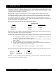
I. INTRODUCTION The Brookfield Programmable DV-II+ Viscometer measures fluid viscosity at given shear rates. Viscosity is a measure of a fluid’s resistance to flow. You will find a detailed description of the mathematics of viscosity in the Brookfield publication ”More Solutions to Sticky Problems” a copy of which was included with your DV-II+. The principal of operation of the DV-II+ is to drive a spindle (which is immersed in the test fluid) through a calibrated spring.
I.1 Components Component Part Number Quantity varies 1 MODEL S 1 varies SSL SSR SSH 1 DV-II+ Viscometer Model S Laboratory Stand Spindle Set with Case LVDV-II+ set of four spindles RVDV-II+ set of six spindles (#2 - #7) HA/HBDV-II+ set of six spindles (#2 - #7) or or For Cone/Plate versions: a spindle wrench, one cone spindle and sample cup, Part No. CPE-44Y replace the spindle set.
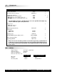
I.3 Specifications Speeds: Interleaved: LV/RV (18 speeds) Sequential: LV/RV (18 speeds) Custom: 54 speeds, user selectable Note: Refer to Appendix F for detailed list of all speeds. Weight: Gross Weight Net Weight Carton Volume 23 lbs. 20 lbs. 1.65 cu. ft. 10.5 kg. 9 kg. 0.
I.4 Installation Note: “IQ, OQ, PQ”, a guideline document for installation, operation and performance validation for your DV-II+ digital viscometer can be downloaded from our web site www.brookfieldengineering.com. 1) Assemble the Model S Laboratory Stand (refer to assembly instructions in Appendix H). 2) Put the viscometer on the stand. 3) Connect the RTD probe to the socket on the rear panel of the DV-II+. 4) The Viscometer must be leveled.
I.5 Safety Symbols and Precautions Safety Symbols The following explains safety symbols which may be found in this operating manual. Indicates hazardous voltages may be present. Refer to the manual for specific warning or caution information to avoid personal injury or damage to the instrument. Precautions If this instrument is used in a manner not specified by the manufacturer, the protection provided by the instrument may be impaired.
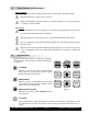
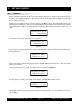
SELECT DISPLAY SELECT DISPLAY Selects the data parameter to be displayed: cP Viscosity (cP or mPa.s) SS Shear Stress (dynes/cm2 or Newtons/m2) SR Shear Rate (1/sec) ENTER AUTO RANGE ENTER/AUTO RANGE ENTER: AUTO RANGE: SELECT SPINDLE Used to execute the currently flashing option. Presents the maximum (100% torque) viscosity attainable using the selected spindle at the current viscometer spindle speed.
I.7 Cleaning Be sure to remove the spindle from the instrument prior to cleaning. Severe instrument damage may result if the spindle is cleaned in place. Instrument and Keypad: Clean with a dry, non-abrasive cloth. Do not use solvents or cleaners. Immersed Components (spindles): Spindles are made of stainless steel. Clean with a nonabrasive cloth and solvent appropriate for sample material. Note: When cleaning, take care not to apply excessive force - it may bend the spindles.
II. II.1 GETTING STARTED Autozero Before readings may be taken, the Viscometer must be Autozeroed. This action is performed each time the power switch is turned on. The display window on the Viscometer will guide you through the procedure as follows: Turn the power switch (located on the rear panel) to the ON position. This will result in the screen display shown in Figure 3. The viscosity measurement range is indicated by the information in the lower left, in this case RV.
II.2 SELECT SPINDLE Spindle Selection LVDV-II+ Viscometers are provided with a set of four spindles and a narrow guardleg; RVDV-II+ Viscometers come with a set of six spindles and a wider guardleg; HADV-II+ and HBDV-II+ Viscometers come with a set of six spindles and no guardleg. (See Appendix E for more information on the guardleg.) The spindles are attached to the viscometer by screwing them onto the lower shaft. Note that the spindles have a left-hand thread.
II.3 SET SPEED Speed Selection, Setting, Running There are 54 speeds programmed into the DV-II+. These speeds correspond to the standard LVT, RVT, HAT and HBT dial models (18 possible speeds altogether) plus 36 additional speeds. The DV-II+ comes with the Sequential Speed Set already selected (see Appendix F). The speed set will start at speed 0.0. It will then scroll up through the LV speeds, pass through speed 0.0 again, and then scroll up through the RV speeds, pass through speed 0.
If an ARROW key is pressed and held the DV-II+ will scroll up (or down) through the speed table. When it reaches the last speed in the list (either at the top or bottom of the list) the speed displayed will “roll-over” to either the first or last speed in the table and the scroll action will continue. When the required speed is displayed, release the ARROW key to halt further scrolling.
SR 40.0 6.0RPM 20.1C % 15.6 Figure 13 One more press of the SELECT DISPLAY key would result in a return to the viscosity screen, as shown in Figure 11. Notes: 1. You may step through the display at any time. This will not interrupt any Viscometer calculations that are in progress. 2. Display of shear rate and shear stress requires selection of appropriate spindles. Otherwise, values displayed will be zero (0).
II.6 Out of Range The DV-II+ gives indications for out-of-range operation. When % (Torque) readings exceed 100% (over-range), the display changes to that shown in Figure 15; EEEE will also appear in the display for % and viscosity or shear stress: cP EEEE 10 RPM 20.1C % EEEE Figure 15 You must change either speed or spindle to correct this condition. If you operate at spindle speeds that produce % (Torque) below 10.
II.7 Temperature Display The DV-II+ displays the temperature measured by its RTD temperature probe. Temperature may be displayed in either ˚C (Centigrade) or ˚F (Fahrenheit) units, depending upon selection from the Options menu. As received, the default temperature display will be in ˚C (Centigrade) units as shown in the Figure 19: cP 123.4 10 RPM 20.1C % 19.
For the case of CGS units with non-exponential results: 1 10 20 30 40 RPM=XXX M=XXXXX S=XX %=XXX.X cP=XXXXX and CGS units with exponential results. 1 10 20 30 D/CM2=XXXXX 40 RPM=XXX M=XXXXX S=XX %=XXX.X cP=XXXeX 50 and SI units with exponential results. 1 10 20 30 40 60 60 RPM=XXX M=XXXXX S=XX %=XXX.X mPas=XXXeX N/M2=XXXeX 60 ZXX=XX 80 ZXX=XX 70 1/SEC=XXXXX T=XX.XC 50 80 70 1/SEC=XXXXX T=XX.XC 50 RPM=XXX M=XXXXX S=XX %=XXX.X mPas=XXXXX N/M2=XXXXX 70 1/SEC=XXXXX T=XX.
Non-Newtonian fluid behavior can result in the measured viscosity changing if the spindle and/ or speed is changed. See our publication, “More Solutions to Sticky Problems,” for more detail. Turn on motor. Allow time for the indicated reading to stabilize. The time required for stabilization will depend on the speed at which the Viscometer is running and the characteristics of the sample fluid. For maximum accuracy, readings below 10% should be avoided. Record values. 4.
III. OPTIONS III.1 OPTIONS TAB Introduction to OPTIONS The OPTIONS/TAB key provides access to the configuration (Setup) of the DV-II+ Viscometer as well as special functions that can enhance the user's ability to make viscosity measurements. The Options menu, shown in Table 1, gives a complete picture of the various configuration choices and special functions.
OPTIONS TAB ENTER AUTO RANGE MOTOR ON/OFF ESCAPE OPTIONS/TAB - Toggles between options. ENTER/AUTORANGE - Accepts the currently flashing option and moves user to next level (if applicable) of the selected option. MOTOR ON/OFF/ESCAPE - Cancels current operation and backs user out one menu level. Repeated pressing will back the user out to the default screen.
Selecting an Option The following is a quick reference for entering and using the OPTIONS menu: Press OPTIONS To enter Options Menu TAB or Press To scroll to a specific option For Options: Press Press OPTIONS TAB ENTER AUTO RANGE To toggle between the choices available for a specific option when indicated To select the flashing option III.
L°F(FAHRENHEIT) CGS UNITS L°C(CENTIGRADE) CGS UNITS L°F(FAHRENHEIT) CGS UNITS L°F(FAHRENHEIT) SI UNITS LCGS UNITS SEQUENTIAL LCGS UNITS INTERLEAVE LSEQUENTIAL PRINT SERIAL LSEQUENTIAL PRINT PARALLEL LPRINT SERIAL DATA AVERAGING LCGS UNITS CUSTOM SPEEDS OPTIONS TAB Figure 25 III.2.1 Temperature Display The DV-II+ viscometer can display temperature in either degrees Centigrade or degrees Fahrenheit.
L°F(FAHRENHEIT) CGS UNITS Figure 28 A press of the OPTIONS/TAB key at this point allows the user to “toggle” between the two available data display units as shown in Figure 29: L°F(FAHRENHEIT) CGS UNITS L°F(FAHRENHEIT) SI UNITS Figure 29 Pressing the ENTER/AUTORANGE key selects the display units, which are flashing, followed by an exit of the Setup menu. You must press the ENTER/AUTORANGE key to select the flashing option. III.2.
III.2.3.2 Custom Speeds Pressing the ENTER/AUTORANGE key when Custom Speeds is displayed results in the following screen display: .01 °0.0 Figure 32 Fifty-four (54) speeds are available for custom speed set selection (see Appendix F). You are allowed to select up to nineteen (19) of these 54 available speeds. Speed 0.0 is automatically included as one of the nineteen (19) speeds. Selecting a speed (or deleting a speed) is accomplished by pressing the SET SPEED key while the desired speed is blinking.
Step 2 is repeated indefinitely until the viscometer is shut off or the user selects a different number of readings to average. The number of readings to be averaged will include zero (0) as an average so that this option may effectively be turned off without turning the viscometer off. Notes: 1. 2. The data averaging will only be applied to the data displayed by the viscometer. No data averaging will be applied to the torque analog output signal.
III.3.1 Time to Stop On entry, the user is presented with the following screen display: TIMED STOP SET MIN’S: 00 Figure 37 Note: If a time interval has already been set, the user may skip the time interval input and go directly to the speed input screen (Figure 39) by pressing the ENTER/AUTORANGE key. Using the UP and DOWN ARROW keys, the user enters a value for the minutes portion of the time ramp. This value can be as high as 59 minutes.
That done, the user is presented with the following screen: TIMED STOP ENTER TO START Figure 40 At this point the user must press the ENTER/AUTORANGE key to begin the timed stop operation. Any other key press will be ignored except the MOTOR ON/OFF/ESCAPE key which will cancel the process and take the user back to the screen of Figure 36 where you will have to begin all over again. We will assume that the user pressed the ENTER/AUTORANGE key.
standard print string to the attached printer as many times as the user presses the PRINT key. In addition, the PRINT key can be pressed during the actual measurement to obtain instantaneous data. Pressing any other key will exit this mode and return the viscometer to normal operation. III.3.
a screen similar to Figure 47 for the duration of the timed torque run: TORQUE = 24.2% MIN: 15 SEC: 13 Figure 47 Note: When this mode has begun, a press of the MOTOR ON/OFF/ESCAPE key will cancel the time to torque sequence and return the user to the screen of Figure 35. The seconds display will increment from zero(0) to fifty-nine (59) in one (1) second intervals and the current value of the viscometer torque will be updated continuously.
However, upon starting the timed operation, the DV-II+ will output an initial data string to the printer and then continue printing data strings (at the user defined time interval) for the duration of the timed run. At the end of the timed run, continuous printing will again be disabled and the user may print single strings (of the final data point) at your option until you exit the timed mode.
Activating print selections in the Print mode can only be done by exiting to the main menu and pressing the PRINT key for four (4) seconds. “P%” will flash in front of the torque reading, confirming that you are now in the Print Interval mode. Pressing PRINT for one (1) second thereafter will disable the Print mode and remove the “P%” from the display. III.3.
Refer to Section IV for information on how to create B.E.V.I.S. programs on a PC which can be downloaded to the DV-II+ Programmable Viscometer. Press the ENTER/AUTORANGE key to download a B.E.V.I.S. program as shown in Figure 56: LOAD TO SLOT#1 PRESS ENTER KEY Figure 56 Select a number from one (1) to four (4) using the UP/DOWN ARROW keys assign a storage location for the program to be downloaded. Note: Remember to keep track of what program is in what slot.
RUN PGM SLOT#1 PRESS ENTER Figure 60 Using the UP/DOWN ARROWkeys, select one of the four (4) stored programs. Press the ENTER/ AUTORANGE key. Any attempt to select a program slot that does not contain a program will result in a double beep for each key press. When a valid program slot is selected, the screen in Figure 61 is displayed: PRINT KEY = LIST ENTER KEY = RUN Figure 61 At this point, you may elect to print the B.E.V.I.S.
CP 123.4 55.1C 10 RPM PGM% 63.7 Figure 65 The DVLOADER Software is used to create, save, print, and down load programs to the DV-II+ Programmable Viscometer. The next section explains how to use the DVLOADER software. Brookfield Engineering Labs., Inc. Page 34 Manual No.
IV. DVLOADER SOFTWARE The DVLOADER software is a WINDOWS-based program provided on a 3-1/2" diskette which comes with the Programmable DV-II+ Viscometer. IV.1 B.E.V.I.S. Overview DVLOADER utilizes B.E.V.I.S. (Brookfield Engineering Viscometer Instruction Set), a scripting language that allows for the creation of programs to control the Programmable DV-II+ Viscometer. Programs are created on a PC, then loaded into the viscometer using the DVLoader software.
IV.2 Description of B.E.V.I.S. Commands Command Code WTI WPT WTP WKY Required Parameter Command Description Time (MM:SS) % Torque value (%) Temperature value (°C) 16 character (or less) text message SSN Speed value (RPM) SPI Time (MM:SS) SSP Two digit spindle code STZ PDN N/A N/A PLN 16 character (or less) text message The program waits at this step until the specified time elapses. The program waits at this step until the current % torque equals the specifed value.
IV.3 Creating a B.E.V.I.S. Program Start the DVLOADER software by clicking on its associated icon or by using the File|Run option of the Windows 3.1 Program Manager. For Windows 95, click the Start button; select Run; enter the name of the program to execute {dvloader.exe}; then click OK. The B.E.V.I.S. commands are displayed in a list box on the main screen. This list box displays the commands available for creating programs.
Figure 67 shows the grid where the operator programs are created. It is used to view and edit the B.E.V.I.S. programs. When the software starts, an empty grid appears on the left of the screen. You can choose up to 25 commands for your program. Highlight each command in the list box to the right of this grid, then click on the Insert button to insert that same command into the highlighted line of the grid.
Click the Delete button to delete the B.E.V.I.S. command in the selected row of the program grid. Click the Up button to move the B.E.V.I.S. command in the selected row of the program grid up one row. Click the Down button to move the B.E.V.I.S. command in the selected row of the program grid down one row. Click the Clear button to clear the grid of all B.E.V.I.S. commands. Once cleared, the commands cannot be retrieved. Downloads a B.E.V.I.S.
IV. 5 Example Programs The following example programs can also be found on the DVLoader disk that was included with the DV-II+ Programmable Viscometer: Program 1: Command Pre-shear Command Description Parameter PLN SSN WPT PLN SPI Print text now Set viscometer speed Wait for % torque Print text now Set print interval Preshearing now 50.0 90.0 Collecting data 00:10 SSN WTI Set viscometer speed Wait for time interval 10.
Program 5: Command SSN WTI PDN SSN WTI PDN SSN WTI PDN SSN WTI PDN Variable speed Command Description Set viscometer speed Wait for time interval Print data point now Set viscometer speed Wait for time interval Print data point now Set viscometer speed Wait for time interval Print data point now Set viscometer speed Wait for time interval Print data point now Brookfield Engineering Labs., Inc. Parameter 5.
Appendix A - Cone/Plate Viscometer Set-Up This Cone/Plate version of the DV-II+ uses the same operating instruction procedures as described in this manual. However, the “gap” between the cone and the plate must be verified/adjusted before measurements are made. This is done by moving the plate (built into the sample cup) up towards the cone until the pin in the center of the cone touches the surface of the plate, and then by separating (lowering) the plate 0.0005 inch (0.013mm).
A.2 SETUP 1. Be sure that the Viscometer is securely mounted to the Laboratory Stand, leveled and zeroed with no cone or cup attached and 0% torque is displayed. Bath Outlet 2. Figure A2 shows a typical water bath setup. Connect the sample cup inlet/outlet ports to the water bath inlet and outlet and set the bath to the desired test temperature. Allow sufficient time for the bath to reach the test temperature. 3.
A.3 SETTING THE GAP 1. Move the toggle switch to the right; this will turn on (enable) the Gap Setting Feature. The Pilot (red) light will be illuminated. 2. If the contact light (yellow) is illuminated, turn the micrometer adjustment ring clockwise (as you look down on the instrument) until the light is no longer illuminated (see Figure A5). 3. If the yellow contact light is not illuminated, slowly turn the micrometer adjustment ring in small increments (one or two scale divisions) counter-clockwise.
A.4 VERIFYING CALIBRATION 1. Determine the appropriate sample volume. Refer to Table A6 to determine the correct sample volume required for the spindle to be utilized. 2. Select a Brookfield Viscosity Standard fluid that will give viscosity readings between 10% and 100% of full scale range. Refer to Appendix B for viscosity ranges of cone spindles; ranges listed apply to CPE cones. Do not use a silicone viscosity standard fluid with a viscosity value greater than 5000 cP with a Cone/Plate.
Appendix B - Viscosity Ranges Viscosity ranges shown are for operational speeds 0.1 through 200 rpm. LV Viscometer with LV spindles #1-4 and RV/HA/HB Viscometers with spindles #1-7 Viscosity Range (cP) Viscometer Minimum Maximum LVDV-II+ RVDV-II+ HADV-II+ HBDV-II+ 15 100 200 800 6,000,000 40,000,000 80,000,000 320,000,000 Small Sample Adapter and Thermosel SSA and Thermosel Spindle S S S SC4-14 SC4-15 SC4-16 SC4-18 SC4-21 SC4-25 SC4-27 SC4-28 SC4-29 SC4-31 SC4-34 S 1 Viscosity (cP) LVDV-II+ 58.
DIN Adapter Accessory Viscosity (cP) DAA Spindle LVDV-II+ 85 86 87 0.6 - 5,000 1.8 - 10,000 5.7 - 50,000 HADV-II+ HBDV-II+ Shear Rate sec-1 12.2 - 5,000 36.5 - 10,000 121 - 50,000 48.8 - 5,000 146 - 10,000 485 - 50,000 1.22N 1.29N 1.29N RVDV-II+ 6.1 - 5,000 18.2 - 10,000 61 - 50,000 Spiral Adapter Viscosity (cP) Spiral Spindle LVDV-II+ SA-70 98 - 98,500 Shear Rate sec-1 RVDV-II+ HADV-II+ HBDV-II+ 1,050-1,050,000 2,100-2,100,000 8,400 - 8,400,000 .00677 .67.
The second consideration involves the mechanics of fluid flow. All rheological measurements of fluid flow properties should be made under laminar flow conditions. Laminar flow is flow wherein all particle movement is in layers directed by the shearing force. For rotational systems, this means all fluid movement must be circumferential.
Appendix C - Variables in Viscosity Measurements As with any instrument measurement, there are variables that can affect a Viscometer measurement. These variables may be related to the instrument (Viscometer), or the test fluid. Variables related to the test fluid deal with the rheological properties of the fluid, while instrument variables would include the Viscometer design and the spindle geometry system utilized.
container wall and the spindle surface. A repeatable viscosity test should control or specify the following: 1) 2) 3) 4) 5) 6) 7) 8) Test temperature Sample container size (or spindle/chamber geometry) Sample volume Viscometer model Spindle used Whether or not to attach the guard leg Test speed or speeds (or the shear rate) Length of time or number of spindle revolutions to record viscosity. Brookfield Engineering Labs., Inc. Page 50 Manual No.
Appendix D - Spindle and Model Codes Each spindle has a two digit entry code which is entered via the keypad on the DV-II+. The entry code allows the DV-II+ to calculate Viscosity, Shear Rate and Shear Stress values. Each spindle has two constants which are used in these calculations. The Spindle Multiplier Constant (SMC) used for viscosity and shear stress calculations, and the Shear Rate Constant (SRC), used for shear rate and shear stress calculations.
Table D1 (continued) SC4-14 SC4-15 SC4-16 SC4-18 SC4-21 SC4-25 SC4-27 SC4-28 SC4-29 SC4-31 SC4-34 SC4-37 CPE-40 CPE-41 CPE-42 CPE-51 CPE-52 V-71 V-72 V-73 14 15 16 18 21 25 27 28 29 31 34 37 40 41 42 51 52 71 72 73 125 50 128 3.2 5 512 25 50 100 32 64 25 0.327 1.228 0.64 5.12 9.83 2.62 11.10 53.50 0.4 0.48 0.2929 1.32 0.93 0.22 0.34 0.28 0.25 0.34 0.28 0.36 7.5 2 3.8 3.84 2 NA NA NA Table D2 lists the model codes and spring torque constants for each Viscometer model. Table D2 MODEL LVDV-II+ 2.
The full scale viscosity range for any DV-II+ model and spindle may be calculated using the equation: Full Scale Viscosity Range [cP] = TK * SMC * 10,000 RPM where: TK = DV-II+ Torque Constant from Table D2 SMC = Spindle Multiplier Constant from Table D1 The Shear Rate calculation is: Shear Rate (1/Sec) = SRC * RPM where: SRC = Shear Rate Constant from Table D1 Brookfield Engineering Labs., Inc. Page 53 Manual No.
Appendix E - Calibration Procedures The accuracy of the DV-II+ is verified using viscosity standard fluids which are available from Brookfield Engineering Laboratories or your local Brookfield agent. Viscosity standards are Newtonian, and therefore, have the same viscosity regardless of spindle speed (or shear rate). Viscosity standards, calibrated at 25°C, are shown in Table E1 (Silicone Oils) and Table E2 (Mineral Oils).
Brookfield Viscosity Standard Fluid General Information We recommend that Brookfield Viscosity Standard Fluids be replaced on an annual basis, one year from date of initial use. These fluids are pure silicone and are not subject to change over time. However, exposure to outside contaminants through normal use requires replacement on an annual basis. Contamination may occur by the introduction of solvent, standard of different viscosity or other foreign material.
4) Allow 30 minutes for the viscosity standard, sample chamber and spindle to reach test temperature. 5) Measure the viscosity and record the Viscometer reading. Note: The spindle must rotate at least five (5) times before readings are taken. Calibration Procedure for a Thermosel System When a Thermosel System is used, the controller stabilizes the Thermo Container at the test temperature. 1) Put the proper amount of HT viscosity standard fluid into the HT-2 sample chamber.
4) The viscosity standard fluid, together with the spindle, should be immersed in the bath for a minimum of 1 hour, stirring the fluid periodically (operate at 50 or 60 RPM periodically), prior to taking measurements. 5) After 1 hour, check the temperature of the viscosity standard fluid with an accurate thermometer. 6) If the fluid is at test temperature (+/- 0.1°C of the specified temperature, normally 25°C), measure the viscosity and record the viscometer reading.
Interpretation of Calibration Test Results: When verifying the calibration of the DV-II+, the instrument and viscosity standard fluid error must be combined to calculate the total allowable error. The DV-II+ is accurate to (+/-) 1% of any full scale spindle/speed viscosity range. Brookfield Viscosity Standards Fluids are accurate to (+/-) 1% of their stated value.
The calibration of the Brookfield Viscometer/Rheometer is determined using a 600 ml Low Form Griffin Beaker. The calibration of LV and RV series instruments includes the guard leg. The beaker wall (for HA/HB instruments) or the guard leg (for LV/RV instruments) define what is called the "outer boundary" of the measurement. The spindle factors for the LV, RV, and HA/HB spindles were developed with the above boundary conditions.
many viscometer users the true viscosity is not as important as a repeatable day to day value. This repeatable value can be obtained without any special effort for any measurement circumstance. But, it should be known that this type of torque reading will not convert into a correct centipoise value when using a Brookfield factor if the boundary conditions are not those specified by Brookfield. The guard leg is a part of the calibration check of the Brookfield LV and RV series Viscometer/ Rheometer.
Appendix F - Speed Sets The following speed sets and custom speeds are selectable from the SETUP menu option. All speeds are in units of RPM. Interleave Speed 0.0 0.3 0.5 0.6 1.0 1.5 2.0 2.5 3.0 4.0 5.0 6.0 10.0 12.0 20.0 30.0 50.0 60.0 100.0 From LVT RVT LVT RVT LVT RVF RVT LVT RVF RVT LVT RVT LVT RVT LVT RVT LVT RVT Sequential Speed 0.0 0.3 0.6 1.5 3.0 6.0 12.0 30.0 60.0 OR 0.0 0.5 1.0 2.0 2.5 4.0 5.0 10.0 20.0 50.0 100.
Appendix G - Communications When using the Brookfield Computer Cable (Brookfield part # DVP-80), the DV-II+ will output a data string at a rate of approximately 3 times per second. When using the Brookfield Printer Cable (Brookfield Part No. DVP-81), the output rate is 1.0 times per second.
Shear Stress (Dynes/Cm2) = TK * SMC * SRC * Torque = 0.09373 * 32.0 * 0.34 * 62.3 = 63.5 Dynes/Cm2 Brookfield Engineering Labs., Inc. Page 63 Manual No.
DV-II+ Serial and Analog Outputs 1 No Connection 6 Analog Ground 2 No Connection 7 3 Transmit Data (TxD) 8 4 High Speed Print (Note 1) Serial Ground 9 Analog % Torque (Note 2) Analog Temperature (Note 3) High Speed Print (Note 1) 5 Figure G1 Notes: 1. Placing a jumper across pins 4 and 9 causes the DV-II+ to output printer data at a 3 line-per-second rate. No jumper across pins 4 and 9 retains the once-per-second printer output rate. 2. This is a 0-1 volt d.c.
Appendix H - Model S Laboratory Stand VS-35Y MODEL S CLAMP ASSEMBLY 7 6 11 8 1 9 10 VS-17SY MODEL S-E CLAMP ASSEMBLY (EXPLOSION-PROOF) BROOKFIELD LABORATORY VISCOMETER 13 15 14 16 2 12 5 ITEM 1 4 3 EXPLOSION-PROOF CLAMP VS-17Y PARTS 2 3 4 5 6 7 8 9 10 11 12 13 14 15 16 DESCRIPTION PART # VS-34 VS-38 VS-2 VS-3 50S311824S06B 502020032S34Z VS-35 VS-40Y VS-41Y VS-29 VS-29W VS-28 50S103208S25B VSXA-17Y 50S252024E140 VS-46Y VS-45Y QTY.
Unpacking Check carefully to see that all the components are received with no concealed damage. 1 Base, VS-2, with 2 Leveling Screws, VS-3, packed in a cardboard carton 1 Upright Rod, VS-34, with attached Clamp Assembly, VS-35Y Assembly (Refer to Figure H1) 1. Remove the base assembly from the carton. 2. Remove the screw and washer from the upright rod. Place the rod and clamp assembly into the hole in the top of the base.
Appendix I - DVE-50 Probe Clip Probe Clip DVE-50 is supplied with all model DV-II+ Viscometers, DV-III Rheometers, and Digital Temperature Indicators. It is used to attach the RTD temperature probe to the LV Guard Leg (Part No. B-20Y) or 600 ml low form Griffin beaker. Figure H1 is a view of the Probe Clip, showing the hole into which the RTD probe is inserted, and the slot which fits onto the LV guard leg.
Appendix J - Fault Diagnosis and Troubleshooting Listed are some of the more common problems that you may encounter while using your Viscometer. ❏ Spindle Does Not Rotate ✓ Make sure the viscometer is plugged in. ✓ Check the voltage rating on your viscometer (115, 220V); it must match the wall voltage. ✓ Make sure the motor is ON and the desired rpm is selected. ❏ Spindle Wobbles When Rotating or Looks Bent ✓ Make sure the spindle is tightened securely to the viscometer coupling.
❏ Inaccurate Readings ✓ Verify spindle, speed and model selection. ✓ If % readings are under-range (less than 10%), the display will flash; change spindle and/or speed. ✓ “EEE” on the digital display means the unit is over-range (greater than 100%); reduce speed and/or change spindle. ✓ Verify test parameters: temperature, container, volume, method.
❏ No Recorder Response ✓ Be Sure the viscometer is not at ZERO reading. ✓ Be sure the recorder is ON and not on STANDBY. ✓ Verify the range settings. ✓ Check cable leads for clean connection. ❏ Recorder Pen Moves in Wrong Direction ✓ Output polarity reversed • Reverse leads ❏ Viscometer Will Not Communicate with PC ✓ Check the comm port and make sure the correct port is being utilized.
✓ Press ENTER/AUTORANGE. Information similar to Figure J4 will appear on your printer output.
Appendix K - Warranty Repair and Service Warranty Brookfield Viscometers are guaranteed for one year from date of purchase against defects in materials and workmanship. They are certified against primary viscosity standards traceable to the National Institute of Standards and Technology (NIST). The Viscometer must be returned to Brookfield Engineering Laboratories, Inc. or the Brookfield dealer from whom it was purchased for no charge warranty service. Transportation is at the purchaser’s expense.
a Packaging Instructions to Return a Viscometer for Repair or Calibration ❏ Remove and return all spindles (properly packed for shipping). ❏ Clean excess testing material off the instrument. F I G U R E K 1 ❏ Include MSDS sheets for all materials tested with this instrument. ❏ Support pointer shaft with white, nylon shipping cap, as shown in Figure K1, or with white plastic shipping cap originally supplied with instrument. ❏ Pack the instrument in its original case.
Providing us with the following information will help us to service your equipment more quickly and efficiently. Please photocopy, fill out and return a copy of this form with your instrument. Brookfield recommends that all viscometers be returned for annual calibration to ensure that your equipment continues to provide the same accuracy you have come to expect from Brookfield products.
BY: TEST INFORMATION: SAMPLE MODEL SPINDLE RPM DIAL READING % TORQUE FACTOR VISCOSITY cP SHEAR RATE TEMP °C TIME NOTES Page 75 Manual No. M/97-164-F1 102 CONCLUSIONS: BROOKFIELD ENGINEERING LABORATORIES, INC. • 11 Commerce Boulevard • Middleboro, MA 02346 • TEL: 508-946-6200 or 800-628-8139 FAX: 508-946-6262 • www.brookfieldengineering.com This tear-off sheet is a typical example of recorded test data. Please photocopy and retain this template so that additional copies may be made as needed.