
Troubleshooting guide


6
Nieco Corporation - Model 9025
B. INSTALLATION
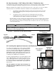
B.1 Pre-Installation
Uncrate the broiler and inspect for shipping damage. Remove the tape securing the machine parts, and
install the parts in their proper location. Refer to the Parts and Location section of this manual. If there
are obvious or concealed damages to any part of the broiler, please contact your freight carrier. The fac-
tory warranty does not cover freight damage.
B.2 Mounting
Follow the mounting instructions if this function is not performed by the installer.
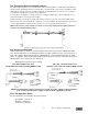
B.3 Leveling
The grease drain system is based on a gravity-flow design. Therefore, it is extremely important to level
the broiler during installation. Use levelling shims (P/N 11936).
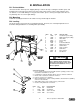
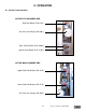
ITEM P/N QTY DESCRIPTION
1 11939 1 Left Stand Leg Assembly
2 11940 1 Right Stand Leg Assembly
3 10803 1 Shear Plate
4 10410 1 Freezer Stop
5 95099 4 Caster
6 11881 1 Control Pad Bracket
7 11089 1 Quick Release Pin
8 10476 8 3/8X7/8” Bolt
9 11888 16 3/8X1 1/4” Bolt
10 10475 8 3/8X2” Bolt
11 10477 16 3/8” Lock Nut
12 5599 32 3/8” Washer
CAUTION
Prior to mating stand to broiler, and
with stand in operating location, verify
that stand is level within 1/8”. If not,
shim as required.
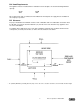
SHIM INSTALLATION:
1. Prior to mating stand to broiler and with stand in operating position, verify
that stand is level within an 1/8” inch.
2. If shimming is required, determine which caster(s) should be shimmed.
3. Elevate side of stand to be shimmed off of floor.
4. Remove caster(s) to be shimmed.
5. When installing shims, remove existing hardware, discard washers (ITEM 2),
and reuse nuts and bolts.
6. After adding shim(s) and securing caster(s), lower broiler.
7. Check to verify that broiler is now level.
ITEM P/N QTY DESCRIPTION
1 11936 AR Stand Shim
2 5599 REF 3/8” Washer
3 11888 REF 3/8X1 1/4” Bolt
4 10477 REF 3/8” Locknut