
Hardware Reference Manual (Supporting Fabric OS v6.1.1_enc) User guide

Brocade Encryption Switch Hardware Reference Manual 23
53-1001117-02
Chapter
3
Maintaining the switch
In this chapter
This chapter provides information about operating and maintaining the switch and includes these
topics.
•Interpreting LEDs. . . . . . . . . . . . . . . . . . . . . . . . . . . . . . . . . . . . . . . . . . . . . . . 23
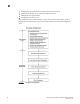
•Interpreting POST results . . . . . . . . . . . . . . . . . . . . . . . . . . . . . . . . . . . . . . . . 28
•Diagnostic testing . . . . . . . . . . . . . . . . . . . . . . . . . . . . . . . . . . . . . . . . . . . . . . 29
•Checking the FRUs . . . . . . . . . . . . . . . . . . . . . . . . . . . . . . . . . . . . . . . . . . . . . 29
Interpreting LEDs
System activity and status can be determined through the activity of the LEDs on the switch. There
are three possible LED states: no light, a steady light, and a flashing light. The lights are green or a
combination of green and amber.
NOTE
The LEDs may flash during boot, POST, or other diagnostic tests. This is normal and does not indicate
a problem.
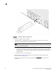
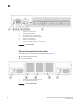
LEDs on the port side of the switch
The port side of the switch has the following LEDs (Figure 10):
• One system status LED (above) on the left side
• One system power LED (below) on the left side
• One Ethernet link LED at the Ethernet management port
• One Ethernet activity LED at the Ethernet management port
• One link LED at each GE port
• One activity LED at each GE port
• One port status LED for each Fibre Channel port.