
Hardware Installation Guide User Manual
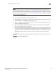
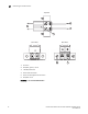
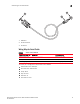
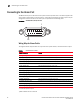
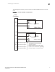

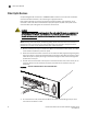
Table Of Contents
- Contents
- Figures
- Tables
- About This Document
- In this chapter
- Introduction
- In this chapter
- Installing the Switch
- In this chapter
- Making Network Connections
- In this chapter
- Troubleshooting
- Cables
- Specifications
- Caution and Danger Notices: English / French
- Caution and Danger Notices: German / Spanish / Chinese
- Glossary
- Index

Brocade 6910 Ethernet Access Switch Hardware Installation Guide 21
53-1002650-02
2
Connecting to the Alarm Port
The following figure shows the pinout information for the DB-15 ALARM connector on the front
panel.
FIGURE 20 EXTERNAL ALARM I/O CONNNECTORS
1
11
6
2
12
7
9
10
3
4
NO
COM
Major Alarm
NC
NO
COM
Alarm
Connector
External Alarm Input 1
External Alarm Input 2
External Alarm Input 3
External Alarm Input 4
To backplane via internal signal
converter circuits.
External input uses dry relay contact
to pins 14, 15, 13 and 8 for grounding.
For active alarm, the relay is closed.
NC
Minor Alarm