
Hardware Installation Guide User Manual
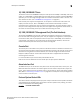
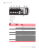
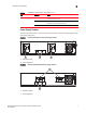

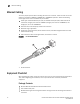
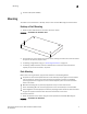
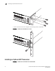
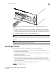
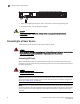
Table Of Contents
- Contents
- Figures
- Tables
- About This Document
- In this chapter
- Introduction
- In this chapter
- Installing the Switch
- In this chapter
- Making Network Connections
- In this chapter
- Troubleshooting
- Cables
- Specifications
- Caution and Danger Notices: English / French
- Caution and Danger Notices: German / Spanish / Chinese
- Glossary
- Index
Description of Hardware
Brocade 6910 Ethernet Access Switch Hardware Installation Guide 7
53-1002650-02
1
Power Supply Sockets
There are two power sockets on the front panel of each switch, as well as two grounding points for
each power supply inlets.
FIGURE 7 Brocade 6910 Switch - AC Power Supply Sockets
1. AC Power Socket
2. Grounding Points
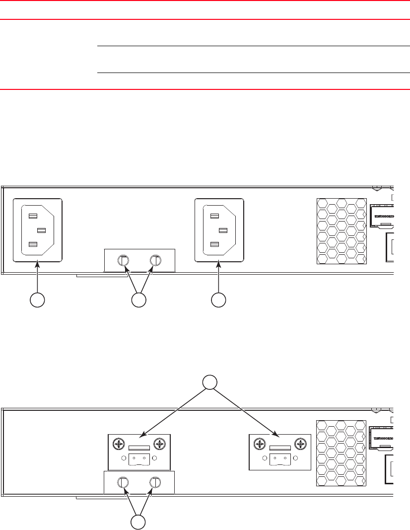
FIGURE 8 Brocade 6910 Switch-DC Power Supply Sockets
1. DC Power Socket
2. Grounding Points
TABLE 2 1000 Mbps PORT STATUS / SFP LEDs (1~12)
LED Condition Status
Port Status (1~12) On/Flashing Green Port has established a valid 1000 Mbps network connection.
Flashing indicates activity.
On/Flashing Amber Port has established a valid 10/100 Mbps network
connection. Flashing indicates activity.
Off There is no valid link on the port.
2
1 1
2
1