
Hardware Installation Guide User Manual


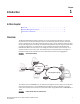
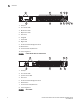
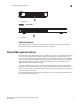

Table Of Contents
- Contents
- Figures
- Tables
- About This Document
- In this chapter
- Introduction
- In this chapter
- Installing the Switch
- In this chapter
- Making Network Connections
- In this chapter
- Troubleshooting
- Cables
- Specifications
- Caution and Danger Notices: English / French
- Caution and Danger Notices: German / Spanish / Chinese
- Glossary
- Index

2 Brocade 6910 Ethernet Access Switch Hardware Installation Guide
53-1002650-02
1
Overview
1. AC Input
2. Port Status LEDs
3. Minor Alarm LED
4. Major Alarm LED
5. Alarm Port
6. Diag LED
7. Power LED
8. Mgmt LED
9. RJ-45 Console & Management Ports
10. Reset Button
11. Combination RJ-45/SFP Ports
12. Grounding Points
FIGURE 3 FRONT PANEL Brocade 6910 Switch
1. DC Input
2. Port Status LEDs
3. System Status LEDs
4. Alarm Port
5. RJ-45 Console & Management Ports
6. Reset Button
7. Combination RJ-45/SFP Ports
8. Grounding Points
FIGURE 4 SIDE PANEL
5
2
4
1
3
6
78
9
1011
12
1
3
78
5
2
4
6