
Technical data


124 ServerIron ADX Advanced Server Load Balancing Guide
53-1002435-03
High availability designs with TCS
2
ServerIronADX(config)# server cache-group 1
ServerIronADX(config-tc-1)# prefer-router-cnt 0
ServerIronADX(config-tc-1)# cache-name cache1
ServerIronADX(config-tc-1)# cache-name cache2
ServerIronADX(config-tc-1)# no http-cache-control
ServerIronADX(config-tc-1)# exit
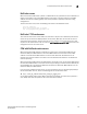
Active-standby TCS
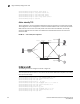
TCS is supported in an active-standby configuration. Figure 27 illustrates a sample active-standby
TCS configuration. In this configuration, one of the ServerIron ADXs serves as the active ServerIron
ADX, while the other remains in standby mode. If the active ServerIron ADX fails, the standby
ServerIron ADX assumes the duties of the failed ServerIron ADX and becomes the new active
ServerIron ADX.
FIGURE 30 Active-standby TCS configuration
Configuring router R1
The following commands configure router R1 in Figure 27.
NOTE
This example shows commands that are valid on the ServerIron ADX device only when it is running
the Layer 3 router image.
ServerIronADX(config)# vlan 1 name DEFAULT-VLAN by port
ServerIronADX(config-vlan-1)# router-interface ve 1
ServerIronADX(config-vlan-1)# exit
ServerIronADX(config)# vlan 200 by port
ServerIronADX(config-vlan-1)# untagged ethe 9 to 16 ethe 26
ServerIronADX(config-vlan-1)# router-interface ve 2
ServerIronADX(config-vlan-1)# exit
ServerIronADX(config)# vlan 3 by port
ServerIronADX(config-vlan-1)# untagged ethe 17 to 18
ServerIronADX(config-vlan-1)# router-interface ve 3
ServerIronADX(config-vlan-1)# exit
Port e1/1
SI-B
Port e1/13
Port e1/10
Port e1/5
Port e1/13
Port e1/5
Port e1/10
Port e1/1
Port e1
Port e3
RouterServer
Layer 2 Switch
Layer 2 Switch
Cache1
Client
Client
195.92.10.6
195.92.10.1
195.92.10.5
195.92.10.22
SI-A