
Technical data


2 ServerIron ADX Advanced Server Load Balancing Guide
53-1002435-03
SIP overview
1
SIP packet flow
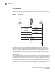
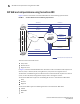
Figure 1 demonstrates the basic operation of SIP; location of an endpoint, signal of a desire to
communicate, negotiation of session parameters to establish the session, and tear-down of the
session after completion.
FIGURE 1 SIP packet flow
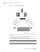
The example in Figure 1 shows packet exchange between two SIP clients, also known as User
Agent Clients (UACs). In the figure each message is labeled with the letter "F" and a number for
reference. The session established between the two end-clients is facilitated by the SIP proxy
server. User1 "calls" User2 using a SIP identity, a type of Uniform Resource Identifier (URI) called a
SIP URI. The SIP URI is similar to an e-mail address, typically containing a username and a host
name. In this case, it is sip:user1@brocade.com, where brocade.com is the domain of User1's SIP
service provider.
SIP is based on an HTTP-like request-and-response transaction model. Each transaction consists of
a request that invokes a particular method, or function, on the server, and at least one response. In
this example, the transaction begins with User1's SIP phone sending an INVITE request addressed
to User2's SIP URI. The INVITE request contains a number of header fields. The fields present in an
INVITE request include a unique identifier for the call (Call-ID), the destination address, User1's
address, and information about the type of session that User1 wishes to establish with User2. The
INVITE (message F1 in Figure 1) would look like the following example:
user1
IP Phone
user2
IP Phone
INVITE F1
INVITE F2
TRYING F3
RINGING F4
RINGING F5
200 OK F6
200 OK F7
ACK F8
MEDIA FLOW
BYE F9
OK F10
SIP Proxy Server