
Technical data


70 Brocade ServerIron ADX Advanced Server Load Balancing Guide
53-1003441-01
Other transparent cache switching options
2
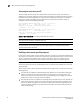
Basic TCS
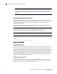
Figure 13 shows the packet flow in a basic TCS configuration. In this example, Flows 1 and 2 are
the Control Channel and Data Channel between the client and cache servers. Both flows are
opened by the client. If the cache server does not have the information, it establishes Flows 3 and
4, which are the Control Channel and Data Channel between the cache server and the real server.
FIGURE 13 Basic TCS for passive FTP
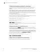
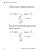
TCS with spoofing
In Figure 14, the cache server is spoofing the client's IP address instead of using its own IP address
when accessing the real server. In Flows 3 and 4, the cache server is using the client's IP address
as the source address instead of using its own IP address.
FIGURE 14 TCS with spoofing for passive FTP