53-1001118-01 18 August 2008 Brocade Encryption Switch QuickStart Guide Supporting Fabric OS v6.1.
Copyright © 2008 Brocade Communications Systems, Inc. All Rights Reserved. Brocade, the Brocade B weave logo, Secure Fabric OS, and SilkWorm are registered trademarks of Brocade Communications Systems, Inc., in the United States and/or in other countries. FICON, IBM BladeCenter are registered trademarks of IBM Corporation in the U.S. and other countries.
Overview This QuickStart guide is intended as an overview to help experienced installers unpack, install, and configure a Brocade Encryption Switch quickly. For detailed installation and configuration instructions, refer to the Brocade Encryption Switch Hardware Reference Manual. This guide include these topics. • Port side of the switch . . . . . . . . . . . . . . . . . . . . . . . . . . . . . . . . . . . . . . . . . . . • Non-port side of the switch . . . . . . . . . . . . . . . . . . . . . . . . . . . .
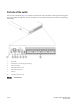
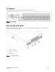
Port side of the switch The port side of the switch (Figure 1) includes the switch power and status LEDs, clustering and re-keying ports, Smart Card reader, management, console, and USB port, and the Fibre Channel ports and their corresponding status LEDs.
Port Numbering The Fibre Channel ports on the switch are numbered from 0 to 31 (Figure 2). FIGURE 2Port numbering Non-port side of the switch The non-port side of the switch (Figure 3) includes the two redundant power supply FRUs, three redundant fan assembly FRUs, and their status LEDs.
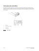
Field-replaceable units (FRUs) The switch has two power supply (Figure 4) and three fan assembly (Figure 5) FRUs that are redundant and hot swappable. The FRUs are capable of functioning universally (100 - 240 VAC input range) without voltage jumpers or switches. The power supply FRUs are identical and interchangeable; the fan assembly FRUs are also identical and interchangeable.
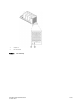
1 Captive screw 2 Fan status LED FIGURE 5 Fan assembly Encryption Switch QuickStart Guide 53-1001118-01 7 of 20
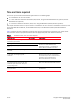
Time and items required You can set up and install the Brocade Encryption Switch in the following ways: • As a standalone unit on a flat surface. • In a 19-in. Electronic Industries Association (EIA) cabinet, using the Fixed Rack Mount Kit (optional) or Slide Rack Mount Kit (optional). • In a mid-mount telecommunications (Telco) rack, using the Mid-Mount (Switch) Rack Kit (optional). This chapter describes how to set up the switch as a standalone unit.
Site preparation and installation guidelines The following steps are required to ensure correct installation and operation. 1. Provide a space that is 2 rack units (2U) high. 1U is equal to 4.45 cm (1.75 in.). 2. Plan to install the switch with the nonport side facing the air-intake aisle. The switch can be installed facing either direction, if serviceability and cooling requirements are met. Ensure that: • A minimum of 53 cubic feet per minute (90.
Items included with the switch The following items are included with the standard shipment of the switch. • The Brocade Encryption Switch, containing two power supplies and three fan assemblies • One accessory kit containing: • Serial cable with an RJ-45 connector. • Two 6 ft. power cords • Rubber feet for setting up the switch as a standalone unit • Brocade family documentation CD Installing a standalone switch To install the switch as a standalone unit, complete the following steps. 1.
Configuring the switch To configure the switch, perform the following tasks. Figure 6 illustrates the flow of these configuration tasks. • Connecting a serial cable between switch and host . . . . . . . . . . . . . . . . . . • Logging in to the serial console port. . . . . . . . . . . . . . . . . . . . . . . . . . . . . . . • Setting the IP address . . . . . . . . . . . . . . . . . . . . . . . . . . . . . . . . . . . . . . . . . . • Logging off the serial console port and disconnecting the serial cable . .
FIGURE 6 12 of 20 Switch configuration Encryption Switch QuickStart Guide 53-1001118-01
Connecting a serial cable between switch and host Follow these steps to connect a serial cable. 1. Remove the plug from the serial port and connect the serial cable provided with the switch. 2. Connect the cable to an RS-232 serial port on the workstation. If the serial port on the workstation is RJ-45 instead of RS-232, remove the adapter on the end of the serial cable and insert the exposed RJ-45 connector into the RJ-45 serial port on the workstation. 3.
Setting the IP address Configure the switch with a static IP address. Setting a static IP address 1. Log into the switch using the default password, which is password. 2. Use the ipaddrset command to set the Ethernet IP address. Enter the IP address in dotted decimal notation as prompted. Ethernet IP Address: 192.168.74.102 3. Complete the rest of the network information as prompted. Ethernet Subnetmask: 255.255.255.0 Ethernet IP Address: 192.168.74.102 Ethernet Subnetmask: 255.255.255.0 4.
Setting the domain ID To set the switch domain ID, follow these steps. 1. Log on to the switch by Telnet, using the admin account. 2. Modify the domain ID if required. The default domain ID is 1. • If the switch is not powered on until after it is connected to the fabric and the default domain ID is already in use, the domain ID for the new switch is automatically reset to a unique value.
switch:admin> date Fri Sep 26 17:01:48 UTC 2008 switch:admin> date "0926123008" Fri Sep 26 12:30:00 UTC 2008 switch:admin> Setting the time zone To set the time zone, follow these steps. 1. If necessary, log on to the switch by Telnet, using the admin account. 2. Enter the tsTimeZone command as follows: switch:admin> tstimezone [--interactive]/ [, timezone_fmt] Use timezone_fmt to set the time zone by Country/City or by time zone ID, such as MST.
switch:admin> tsclockserver LOCL switch:admin> tsclockserver "132.163.135.131" switch:admin> tsclockserver 132.163.135.131 switch:admin> The following example shows how to set up more than one NTP server using a DNS name: switch:admin> tsclockserver "10.32.170.1;10.32.170.2;ntp.localdomain.net" Updating Clock Server configuration...done.
NOTE Each SFP has a 10-pad gold-plated PCB-edge connector on the bottom. The correct position to insert an SFP into the upper row of ports is with the gold edge down. The correct position to insert an SFP into the lower row of ports is with the gold edge up. FIGURE 7 Installing an SFP into an upper port 4. Connect the cables to the transceivers. The cables used in trunking groups must meet specific requirements. For a list of these requirements, see the Fabric OS Administrator’s Guide.
Managing cables ATTENTION The minimum bend radius for a 50 micron cable is 2 in. under full tensile load and 1.2 in. with no tensile load. Cables can be organized and managed in a variety of ways: for example, using cable channels on the sides of the cabinet or patch panels to minimize cable management. Following is a list of recommendations: • Plan for rack space required for cable management before installing the switch. • Leave at least 3.28 ft (1 m) of slack for each port cable.
After completing the pre-initialization tasks, you may need to perform several tasks related to configuring the encryption group. Figure 8 summarizes the flow of the encryption-configuration tasks.