
Technical data


Table Of Contents
- In this guide
- Introduction
- Safety notices
- Danger notices
- Caution notices
- Brocade DCX 8510-4, port side
- Brocade DCX 8510-4, nonport side
- Time and items required for installation
- Site planning and safety guidelines
- Items included with the Brocade DCX 8510-4
- Unpacking and installing the Brocade DCX 8510-4
- Providing power to the Brocade DCX 8510-4
- Managing cables
- High density cabling
- Installing QSFP cables (optional)
- Possible QSFP cable configurations
- Establishing a serial connection and logging on to Brocade DCX 8510-4
- Configuring IP addresses
- Establishing an Ethernet connection
- Customizing a switch name
- Customizing a chassis name
- Setting the Domain ID
- Verifying PID mode
- Installing transceivers
- Confirming software licenses
- Backing up the configuration
Brocade DCX 8510-4 Backbone QuickStart Guide 7 of 24
Publication Number: 53-1002178-01
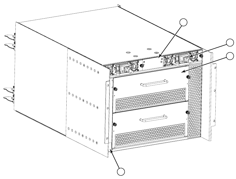
FIGURE 3 Nonport side of the Brocade DCX 8510-4 (sample configuration)
Time and items required for installation
You can set up and install the Brocade DCX 8510-4 in the following ways:
• As a standalone unit on a flat surface.
• In a 19-in. Electronic Industries Association (EIA) cabinet, using a Brocade DCX 8510-4, DCX-4S Rack Mount Kit
(either a 27-31 in. or 18-34 in. kit depending on rack used).
• In a chassis with the Port Side Exhaust Kit (provided) in a Brocade-qualified rack.
• In a mid-mount telecommunications (Telco) rack, using the Mid-Mount Rack Kit available from your Brocade DCX
8510-4 supplier.
This chapter describes how to set up the Brocade DCX 8510-4 as a standalone unit. For rack-mount installation
instructions, refer to the appropriate manual as described in the following table.
The following table describes the main installation and setup tasks, the estimated time required for each, and the
items required to complete the task based on a fully populated Brocade DCX 8510-4 (192 Fibre Channel ports using
the FC16-48 port blades). Configurations with fewer ports require less time. These time estimates assume a
prepared installation site and appropriate power and network connectivity.
1 WWN card bezel (logo plate - WWN card behind) 2 Power supply (2x)
3 Blower assembly (2x) 4 Label with serial number and WWN
1
2
3
4