
Technical data


Table Of Contents
- In this guide
- Introduction
- Safety notices
- Danger notices
- Caution notices
- Brocade DCX 8510-4, port side
- Brocade DCX 8510-4, nonport side
- Time and items required for installation
- Site planning and safety guidelines
- Items included with the Brocade DCX 8510-4
- Unpacking and installing the Brocade DCX 8510-4
- Providing power to the Brocade DCX 8510-4
- Managing cables
- High density cabling
- Installing QSFP cables (optional)
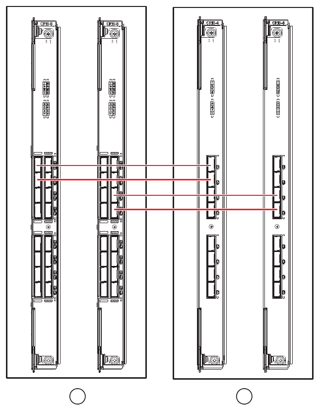
- Possible QSFP cable configurations
- Establishing a serial connection and logging on to Brocade DCX 8510-4
- Configuring IP addresses
- Establishing an Ethernet connection
- Customizing a switch name
- Customizing a chassis name
- Setting the Domain ID
- Verifying PID mode
- Installing transceivers
- Confirming software licenses
- Backing up the configuration
16 of 24 Brocade DCX 8510-4 Backbone QuickStart Guide
Publication Number: 53-1002178-01
FIGURE 7 QSFP cable connections – 8510 sample configuration - parallel type
Establishing a serial connection and logging on to Brocade DCX 8510-4
To establish a serial connection to the console port on the Brocade DCX 8510-4, complete the following steps.
1. Verify that the Brocade DCX 8510-4 is powered on and that POST is complete by verifying that all power LED
indicators on the port, control processor, and core switch blades display a steady green light.
2. Remove the shipping cap from the CONSOLE port on the active CP. Use the serial cable provided with the
Brocade DCX 8510-4 to connect the CONSOLE port on the active CP to a computer workstation. The active CP
blade is indicated by an illuminated (blue) LED.
1 Chassis 1 2 Chassis 2
1 2