
Technical data


Table Of Contents
- In this guide
- Introduction
- Safety notices
- Danger notices
- Caution notices
- Brocade DCX 8510-4, port side
- Brocade DCX 8510-4, nonport side
- Time and items required for installation
- Site planning and safety guidelines
- Items included with the Brocade DCX 8510-4
- Unpacking and installing the Brocade DCX 8510-4
- Providing power to the Brocade DCX 8510-4
- Managing cables
- High density cabling
- Installing QSFP cables (optional)
- Possible QSFP cable configurations
- Establishing a serial connection and logging on to Brocade DCX 8510-4
- Configuring IP addresses
- Establishing an Ethernet connection
- Customizing a switch name
- Customizing a chassis name
- Setting the Domain ID
- Verifying PID mode
- Installing transceivers
- Confirming software licenses
- Backing up the configuration
Brocade DCX 8510-4 Backbone QuickStart Guide 13 of 24
Publication Number: 53-1002178-01
ATTENTION
Do not route the cables in front of the air exhaust vent, which is located at the top of the port side of the chassis.If
you are using the Port Side Exhaust Kit with your Brocade DCX 8510-4, there is also an exhaust vent at the bottom of
the port side of the chassis. Use the vertical cable fingers to keep the cables away from this exhaust vent as well.
FIGURE 4 Vertical cable management finger assemblies
High density cabling
The FC8-64 high density port blade cannot use the standard LC cables because the pitch between optics in the new
mini-SFP (mSFP) transceiver is smaller than in standard SFPs. Patch cables and panels can be used to attach
standard size cabling to the blade if necessary. The figure below illustrates the mSFP to SFP patch cable. See “Best
Practices Guide: High Density Cable Management Solutions” (available at http://www.brocade.com) for cable
management guidelines for high-density port solutions, cable and patch panel part numbers.
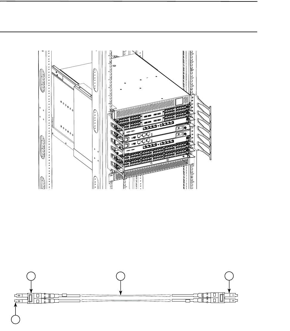
FIGURE 5 Cable design for the mSFP patch cables for the FC8-64 high density port blade
1 mSFP connector 3 1.6 mm cable
2 Duplex clip (black) 4 SFP connector
2 3
4
1