5 53-1002177-05 10 May 2012 Brocade DCX 8510-4 Backbone Hardware Reference Manual ®
Copyright © 2011-2012 Brocade Communications Systems, Inc. All Rights Reserved. Brocade, Brocade Assurance, the B-wing symbol, BigIron, DCX, Fabric OS, FastIron, MLX, NetIron, SAN Health, ServerIron, TurboIron, VCS, and VDX are registered trademarks, and AnyIO, Brocade One, CloudPlex, Effortless Networking, ICX, NET Health, OpenScript, and The Effortless Network are trademarks of Brocade Communications Systems, Inc., in the United States and/or in other countries.
Title Publication number Summary of changes Date Brocade DCX 8510-4 Backbone Hardware Reference Manual 53-1002177-02 Updated filler panel graphics, CP replacement procedures to 7.0, data transmission range information, and rack kit measurement. June 2011 Brocade DCX 8510-4 Backbone Hardware Reference Manual 53-1002177-03 Updated power supply requirements data, power supply replacement information, ISL trunking totals, inter-chassis link information, and CP blade slot numbering.
iv Brocade DCX 8510-4 Backbone Hardware Reference Manual 53-1002177-05
Contents About This Document In this chapter . . . . . . . . . . . . . . . . . . . . . . . . . . . . . . . . . . . . . . . . . . . xv How this document is organized . . . . . . . . . . . . . . . . . . . . . . . . . . . . xv Supported hardware and software . . . . . . . . . . . . . . . . . . . . . . . . . . xvi What’s new in this document . . . . . . . . . . . . . . . . . . . . . . . . . . . . . . . xvi Document conventions . . . . . . . . . . . . . . . . . . . . . . . . . . . . . . . . . . . .
Preparing for Brocade DCX 8510-4 installation . . . . . . . . . . . . . . . . 14 Unpacking and installing the Brocade DCX 8510-4 . . . . . . . . . . . . . 16 Items included with the Brocade DCX 8510-4 . . . . . . . . . . . . . . . . . 17 Providing power to the Brocade DCX 8510-4 . . . . . . . . . . . . . . . . . . 18 Port numbering . . . . . . . . . . . . . . . . . . . . . . . . . . . . . . . . . . . . . . . . . . 18 Chassis slots . . . . . . . . . . . . . . . . . . . . . . . . . . . . . . . . . . . . . . .
Determining the status of a port, application, or encryption blade . . . . . . . . . . . . . . . . . . . . . . . . . . . . . . . . . . . . . . . . . 44 Blade illustrations . . . . . . . . . . . . . . . . . . . . . . . . . . . . . . . . . . . .44 Determining the status of a control processor blade (CP8) . . . . . . . 50 Determining the status of a core switch blade (CR16-4) . . . . . . . . . 51 Determining the status of a power supply. . . . . . . . . . . . . . . . . . . . .
Power supply removal and replacement . . . . . . . . . . . . . . . . . . . . . . 78 Time and items required . . . . . . . . . . . . . . . . . . . . . . . . . . . . . . . 79 Identifying power supplies. . . . . . . . . . . . . . . . . . . . . . . . . . . . . . 79 Removing a power supply . . . . . . . . . . . . . . . . . . . . . . . . . . . . . . 79 Replacing a power supply . . . . . . . . . . . . . . . . . . . . . . . . . . . . . . 80 Blower assembly removal and replacement . . . . . . . . . . . . . . . . . .
Environmental requirements . . . . . . . . . . . . . . . . . . . . . . . . . . . . . .113 Fibre Channel port specifications . . . . . . . . . . . . . . . . . . . . . . . . . .114 Power specifications . . . . . . . . . . . . . . . . . . . . . . . . . . . . . . . . . . . . .114 Power cords . . . . . . . . . . . . . . . . . . . . . . . . . . . . . . . . . . . . . . . . . . . .116 Power cord notice. . . . . . . . . . . . . . . . . . . . . . . . . . . . . . . . . . . .119 Power cord notice (Japan DENAN) . . . .
x Brocade DCX 8510-4 Backbone Hardware Reference Manual 53-1002177-05
Figures Figure 1 Port side of the Brocade DCX 8510-4 (sample configuration) . . . . . . . . . . . . . . . 4 Figure 2 Port side of the Brocade DCX 8510-4 with the port side exhaust kit installed (sample configuration) . . . . . . . . . . . . . . . . . . . . . . . . . . . . . . . . . . . . . . . . . . . . . . . 5 Figure 3 Nonport side of the Brocade DCX 8510-4 (sample configuration) . . . . . . . . . . . . 6 Figure 4 Cable design for the mSFP patch cables for the FC8-64 high density port blade . . . .
xii Figure 33 QSFP cable connections for Brocade DCX 8510 chassis (sample configuration) . . . . . . . . . . . . . . . . . . . . . . . . . . . . . . . . . . . . . . . . . . . . . . 92 Figure 34 DCX 8510 core/edge ICL topology . . . . . . . . . . . . . . . . . . . . . . . . . . . . . . . . . . . . 93 Figure 35 DCX 8510 full mesh ICL topology . . . . . . . . . . . . . . . . . . . . . . . . . . . . . . . . . . . . . 94 Figure 36 CR16-4 core blade . . . . . . . . . . . . . . . . . . . . . . . . . . . .
Tables Table 1 Blades available for the Brocade DCX 8510-4. . . . . . . . . . . . . . . . . . . . . . . . . . . . 7 Table 2 Installation tasks, time, and items required . . . . . . . . . . . . . . . . . . . . . . . . . . . . . 14 Table 3 Port and application blade LED descriptions . . . . . . . . . . . . . . . . . . . . . . . . . . . . 48 Table 4 CP blade LED descriptions . . . . . . . . . . . . . . . . . . . . . . . . . . . . . . . . . . . . . . . . . . . 50 Table 5 CR blade LED descriptions. . .
xiv Brocade DCX 8510-4 Backbone Hardware Reference Manual 53-1002177-05
About This Document In this chapter • How this document is organized . . . . . . . . . . . . . . . . . . . . . . . . . . . . . . . . . . xv • Supported hardware and software. . . . . . . . . . . . . . . . . . . . . . . . . . . . . . . . . xvi • What’s new in this document . . . . . . . . . . . . . . . . . . . . . . . . . . . . . . . . . . . . . xvi • Document conventions . . . . . . . . . . . . . . . . . . . . . . . . . . . . . . . . . . . . . . . . . . xvi • Notice to the reader . . . . . . . . . . . . .
Supported hardware and software • Appendix C, “Diagnostics and Troubleshooting,” provides methods for receiving system-wide or component-level status and interpreting POST and boot activities and diagnostic tests; it also includes troubleshooting tips. • Appendix D, “Port Numbering Template,” contains templates where you can record the port numbering sequence for the port blades.
Document conventions Command syntax conventions Command syntax in this manual follows these conventions: command Commands are printed in bold. --option, option Command options are printed in bold. -argument, arg Arguments. [] Optional element. variable Variables are printed in italics. In the help pages, values are underlined or enclosed in angled brackets < >. ... Repeat the previous element, for example “member[;member...]” value Fixed values following arguments are printed in plain font.
Notice to the reader CAUTION A Caution statement alerts you to situations that can be potentially hazardous to you or cause damage to hardware, firmware, software, or data. DANGER A Danger statement indicates conditions or situations that can be potentially lethal or extremely hazardous to you. Safety labels are also attached directly to products to warn of these conditions or situations. Notice to the reader This document may contain references to the trademarks of the following corporations.
Getting technical help For additional Brocade documentation, visit the Brocade website: http://www.brocade.com Release notes are available on the MyBrocade website and are also bundled with the Fabric OS firmware. Other industry resources For additional resource information, visit the Technical Committee T11 website. This website provides interface standards for high-performance and mass storage applications for Fibre Channel, storage management, and other applications: http://www.t11.
Document feedback In addition, the chassisShow command displays the Brocade DCX 8510-4 serial number, as well as information about the port and application blades, and other field-replaceable units (FRUs). 3. License ID Use the licenseIdShow command to display the license ID. 4. World Wide Name (WWN) Use the wwn command to display the switch WWN.
Chapter Brocade DCX 8510-4 Backbone Overview 1 In this chapter • Brocade DCX 8510-4 features . . . . . . . . . . . . . . . . . . . . . . . . . . . . . . . . . . . . . 1 • Brocade DCX 8510-4 hardware components . . . . . . . . . . . . . . . . . . . . . . . . . 2 • Brocade DCX 8510-4 blades . . . . . . . . . . . . . . . . . . . . . . . . . . . . . . . . . . . . . . 7 • High availability . . . . . . . . . . . . . . . . . . . . . . . . . . . . . . . . . . . . . . . . . . . . . . . . . 8 • Reliability . . . .
1 Brocade DCX 8510-4 hardware components • Beginning with Fabric OS v7.0.1, up to nine chassis can be connected with the use of 4x16 Gbps quad SFP (QSFP) inter-chassis links (ICLs). Fabric OS v7.0.0 permits up to six chassis to be linked. • Support for high-performance port blades running at 2, 4, 8, 10, or 16 Gbps, enabling flexible system configuration.
Brocade DCX 8510-4 hardware components 1 • Modular, hot-swappable encryption blades: - FS8-18: 16-port, up to 4 blades per chassis, supporting in-flight data cryptographic (encryption/decryption) and data-compression capabilities. • Modular, hot-swappable field-replaceable units (FRUs): - Two blower assemblies. - Two power supplies (100-240 VAC auto-sensing). - At 110 VAC (nominal): A minimum of two power supplies is required, regardless of the number of port or application blades.
1 Brocade DCX 8510-4 hardware components Port side of the Brocade DCX 8510-4 NOTE Airflow in the Brocade DCX 8510-4 is from the nonport side to the left side and port side of the chassis (viewed from the port side) and out the exhaust vents. If you use the Port Side Exhaust Kit, the air vents are all on the port side of the chassis (see Figure 2). Figure 1 displays a sample configuration of the port side of the Brocade DCX 8510-4.
Brocade DCX 8510-4 hardware components FIGURE 2 1 Port side of the Brocade DCX 8510-4 with the port side exhaust kit installed (sample configuration) Brocade DCX 8510-4 Backbone Hardware Reference Manual 53-1002177-05 5
1 Brocade DCX 8510-4 hardware components Nonport side of the Brocade DCX 8510-4 Figure 3 displays a sample configuration of the nonport side view of the Brocade DCX 8510-4.
Brocade DCX 8510-4 blades 1 Brocade DCX 8510-4 blades Table 1 summarizes the port, application, control processor, and core switch blades that are available for the Brocade DCX 8510-4. TABLE 1 Blades available for the Brocade DCX 8510-4 Description Name Function Brocade DCX 8510-4 control processor blade CP8 The CP8 blade contains the control plane for the chassis. There are two CP8 blades for redundancy.
1 High availability High availability The following features contribute to the Brocade DCX 8510-4 high-availability design: • • • • • • • Redundant, hot-swappable FRUs, including blades, power supplies, blowers, and WWN cards Enhanced data integrity on all data paths Fabric Shortest Path First (FSPF) rerouting around failed links Integration with Simple Network Management Protocol (SNMP) managers Automatic control processor failover Nondisruptive “hot” software code loads and activation Easy configurati
Serviceability 1 Serviceability The Brocade DCX 8510-4 provides the following features to enhance and ensure serviceability: • Modular design with hot-swappable components. • Flash memory that stores two firmware images per control processor. • USB port on control processor blades for most tasks that formerly required an FTP/SCP server, including software and firmware upgrades.
1 Security Security The following list highlights some of the key security features available for the Brocade DCX 8510-4 and for other Brocade enterprise-class products running Fabric OS 7.0.1 or later. For details, contact your Brocade DCX 8510-4 supplier and refer to the Brocade White Paper, “The Growing Need for Security in Storage Area Networks.
Network manageability 1 Network manageability The Brocade DCX 8510-4 has a single domain and is managed as a single element with the Brocade Network Advisor. The Brocade DCX 8510-4 responds to its own IP address and appears as a separate entity to the Telnet protocol and SNMP. All management interfaces, such as Telnet, Web Tools, standards-compliant SMI-S, and Management Server, support a “port N within blade M” naming scheme. The Brocade DCX 8510-4 supports SNMPv1 and SNPMv3.
1 12 Network manageability Brocade DCX 8510-4 Backbone Hardware Reference Manual 53-1002177-05
Chapter 2 Installation of the Brocade DCX 8510-4 In this chapter • Time and items required . . . . . . . . . . . . . . . . . . . . . . . . . . . . . . . . . . . . . . . . . • Preparing for Brocade DCX 8510-4 installation . . . . . . . . . . . . . . . . . . . . . . • Unpacking and installing the Brocade DCX 8510-4 . . . . . . . . . . . . . . . . . . . • Items included with the Brocade DCX 8510-4. . . . . . . . . . . . . . . . . . . . . . . . • Providing power to the Brocade DCX 8510-4 . . . . . . . . . .
2 Preparing for Brocade DCX 8510-4 installation TABLE 2 Installation tasks, time, and items required Installation task Time estimate Items required Site preparation and unpacking Brocade DCX 8510-4 30 minutes 1/2-in. socket wrench (to remove pallet bolts). #2 Phillips screwdriver (for cable management comb). Pallet jack. Hydraulic lift or assisted lift, able to raise to a minimum of 140 cm (55 in.), with a minimum capacity of 113 kg (250 lb).
Preparing for Brocade DCX 8510-4 installation 2 The following steps are required to ensure correct installation and operation. 1. Plan to install the Brocade DCX 8510-4 with the nonport side facing the air-intake aisle. The Brocade DCX 8510-4 can be installed facing either direction, if serviceability and cooling requirements are met. 2.
2 Unpacking and installing the Brocade DCX 8510-4 Unpacking and installing the Brocade DCX 8510-4 Use the following procedure to unpack and install your Brocade DCX 8510-4. CAUTION Use safe lifting practices when moving the product. (C015) NOTE A fully populated Brocade DCX 8510-4 (four FC16-48 port cards, 192 ports) weighs approximately 68 kg (150 lbs) and requires a hydraulic or assisted lift to install it. 1. Unpack the Brocade DCX 8510-4. a. Cut the bands that encircle the packaging. b.
Items included with the Brocade DCX 8510-4 2 Items included with the Brocade DCX 8510-4 The Brocade DCX 8510-4 ships with the following: • Brocade DCX 8510-4 chassis, populated with: - Control processor blades (CP8) - Core switch blades (CR16-4) - Port blades, application blades, and encryption blades (included based on customer specification) - Blade slot filler panels (for slots not filled by blades) Port side exhaust kit (included based on customer specification) WWN cards WWN bezel (logo plate) Pow
2 Providing power to the Brocade DCX 8510-4 Providing power to the Brocade DCX 8510-4 Complete the following steps to provide power to the chassis. DANGER Use the supplied power cords. Ensure the facility power receptacle is the correct type, supplies the required voltage, and is properly grounded. (D004) 1. Connect the two AC power cords to the two power supplies. 2.
Chassis slots 2 • FC16-32 port blade — Ports are numbered from 0 through 15 from right to left on the lower set of ports and 16 through 31 from right to left on the upper set of ports. • FC16-48 port blade — Ports are numbered from 0 through 23 from right to left on the lower set of ports and 24 through 47 from right to left on the upper set of ports. • CR16-4 core blade — Inter-chassis link connectors are numbered from 0 through 7 from right to left.
2 Cable management Cables can be organized and managed in a variety of ways, for example, using cable channels on the sides of the cabinet or patch panels to minimize cable management. Following is a list of recommendations: NOTE You should not use tie wraps with optical cables because they are easily overtightened and can damage the optic fibers. • Plan for rack space required for cable management before installing the switch. • Leave at least 1 m (3.28 ft) of slack for each port cable.
2 Cable management 2 3 mSFP connector Duplex clip (black) 2 4 4 1 1 3 FIGURE 4 1.6 mm cable SFP connector Cable design for the mSFP patch cables for the FC8-64 high density port blade Note that the duplex clip on the mSFP end of the cable is black for easier recognition. See the appendix for a listing of the qualified mSFP optical cables for the FC8-64 port blade. If ISL Trunking is in use, group the cables by trunking group.
2 22 Cable management Brocade DCX 8510-4 Backbone Hardware Reference Manual 53-1002177-05
Chapter 3 Logging In and Configuring the Brocade DCX 8510-4 In this chapter • Configuring the Brocade DCX 8510-4 . . . . . . . . . . . . . . . . . . . . . . . . . . . . . . • Establishing a serial connection to the Brocade DCX 8510-4 . . . . . . . . . . . • Logging in to the serial console port . . . . . . . . . . . . . . . . . . . . . . . . . . . . . . . • Configuring the IP addresses . . . . . . . . . . . . . . . . . . . . . . . . . . . . . . . . . . . . .
3 Establishing a serial connection to the Brocade DCX 8510-4 The configuration information is mirrored to the standby CP blade, which allows the current configuration to remain available even if the active CP blade fails. The configuration information for the Brocade DCX 8510-4 is stored in the WWN cards and the flash memory of the CP blades. The configuration can be backed up to a workstation (uploaded) and then downloaded to the active CP blade if necessary.
Logging in to the serial console port 3 1. Verify that the Brocade DCX 8510-4 is powered on and that POST is complete by verifying that all power LED indicators on the port, control processor, and core switch blades display a steady green light. 2. Remove the shipping cap from the CONSOLE port on the active CP. Use the serial cable provided with the Brocade DCX 8510-4 to connect the CONSOLE port on the active CP to a computer workstation. The active CP blade is indicated by an illuminated (blue) LED.
3 Configuring the IP addresses 1. Log in to the Brocade DCX 8510-4 as admin. The default password is password. At the initial login, you are prompted to enter new admin and user passwords. Make sure to write down the new passwords and keep this information in a secure location. Fabric OS (swDir) swDir login: admin Password: Please change your passwords now. Use Control-C to exit or press 'Enter' key to proceed. swDir:admin> 2. (Optional) Modify passwords. To skip modifying the password, press Ctrl-C.
Logging off the serial console port and disconnecting the serial cable 3 NOTE The addresses 10.0.0.0 through 10.0.0.255 are reserved and used internally by the Brocade DCX 8510-4. External IPs must not use these addresses. 3. Set up the CP0 IP address by entering the ipaddrset -cp 0 command: swDir:admin> ipAddrSet -cp 0 Enter the information at the prompts. 4. Set up the CP1 IP address by entering the ipaddrset -cp 1 command: swDir:admin> ipAddrSet -cp 1 Enter the information at the prompts.
3 Customizing a switch name NOTE Connecting the CP blades to a private network/VLAN is recommended. By establishing an Ethernet connection, you can complete the Brocade DCX 8510-4 configuration using either a serial session, Telnet, or management applications, such as Web Tools or Brocade Network Advisor. Perform the following steps to establish an Ethernet connection to the Brocade DCX 8510-4. 1. Remove the shipping plug from the Ethernet port on the active CP blade. 2.
Setting the domain ID 3 2. Enter chassisName by itself to show the name. switch:admin> chassisname DCX8510_chassis 3. Record the new name for reference. Setting the domain ID Each switch in the fabric must have a unique domain ID. The domain ID can be manually set through the configure command or can be automatically set. The default domain ID for the Brocade DCX 8510-4 is 1. Use the fabricShow command to view the already assigned domain IDs. 1. Enter switchDisable to disable the Brocade DCX 8510-4. 2.
3 Setting the date and time • HH is the hour; valid values are 00 through 23. • MM is minutes; valid values are 00 through 59. • yy is the year; valid values are 00 through 99 (values greater than 69 are interpreted as 1970 through 1999, and values less than 70 are interpreted as 2000 through 2069).
Verifying the PID mode 3 Synchronizing local time To synchronize the local time of the principal or primary switch with that of an external NTP server, follow these steps. 1. If necessary, log on to the switch by Telnet, using the admin account. 2. Enter the tsClockServer command: switch:admin> tsclockserver "" where ntp1 is the IP address or DNS name of the first NTP server, which the switch must be able to access. The variable ntp2 is the second NTP server and is optional.
3 Determining installed software licenses You can check the PID setting using the configshow command as in the following example. You can use the | grep -i pid qualifier to pinpoint the PID information. switch:admin> configshow | grep -i pid fabric.ops.mode.pidFormat:1 fabric.wwnPidMode:1 The 1 indicates that the WWN Based persistent PID feature is enabled. The default value is 0 for disabled.
Installing transceivers and attaching cables 3 The ports are color-coded to indicate which can be used in the same port group for trunking (trunking port groups can be up to eight ports). The ports and cables used in trunking groups must meet specific requirements. Refer to the Fabric OS Administrator’s Guide for more information. 1. Add the optical transceivers and cables to the Fibre Channel ports.
3 Installing transceivers and attaching cables 4. Verify the Brocade DCX 8510-4 and connector and port status using the switchShow -qsfp command. A sample of the command output is shown below. The example is from a DCX 8510-4 with a core blade installed in slot 3. Some details for the 8510-8 will be different, but the reported information for the QSFPs will be similar. Note that the State reported for an unconnected QSFP (shown QSFP 0 and Ports 0-3 below) is No_SigDet.
Managing cables 748 3 28 7 -----id 10:00:00:05:1e:39:e4:5a trunkmaster 749 3 29 7 -----id 10:00:00:05:1e:39:e4:5a trunkmaster 750 3 30 7 -----id 10:00:00:05:1e:39:e4:5a trunkmaster 751 3 31 7 -----id 10:00:00:05:1e:39:e4:5a trunkmaster 16G Online FC name (Trunk master) 16G Online FC name (Trunk master) 16G Online FC name (Trunk master) 16G Online FC name (Trunk master) 3 E-Port E-Port E-Port E-Port Managing cables Cables can be organized and managed in a variety of ways: for example, using cable channe
3 Verifying correct operation and backing up the configuration Verifying correct operation and backing up the configuration To verify correct operation and back up the Brocade DCX 8510-4 configuration, follow these steps. For information about LED patterns, see Table 3 on page 48, Table 4 on page 50, and Table 5 on page 52. Complete the following steps to back up the configuration for the Brocade DCX 8510-4. 1. Check the LEDs to verify that all components are functional. 2.
Powering off the Brocade DCX 8510-4 3 Are you sure you want to shutdown the switch [y/n]?y HA is disabled Stopping blade 1 Shutting down the blade.... Stopping blade 2 Shutting down the blade.... Stopping blade 8 Shutting down the blade.... Broadcast message from root (pts/1) Tue Aug 23 14:23:06 2010... The system is going down for system halt NOW !! 2. Power off the chassis by flipping the AC power switches on the power supplies to O (LEDs inside AC power switches should turn off).
3 38 Powering off the Brocade DCX 8510-4 Brocade DCX 8510-4 Backbone Hardware Reference Manual 53-1002177-05
Chapter 4 Monitoring System Components In this chapter • Monitoring overview . . . . . . . . . . . . . . . . . . . . . . . . . . . . . . . . . . . . . . . . . . . . • Determining the status of a port, application, or encryption blade . . . . . . . • Determining the status of a control processor blade (CP8) . . . . . . . . . . . . . • Determining the status of a core switch blade (CR16-4) . . . . . . . . . . . . . . . • Determining the status of a power supply . . . . . . . . . . . . . . . . . . . . . . .
4 Monitoring overview 0 1 0 820000 10:00:00:05:1e:f8:a0:b4 1 1 1 820100 10:00:00:05:33:26:0e:65 2 1 2 820200 10:00:00:05:33:48:5e:f5 3 1 3 820300 10:00:00:05:1e:f8:a0:b3 4 1 4 820400 10:00:00:05:33:26:10:15 5 1 5 820500 10:00:00:05:1e:f8:a0:b1 6 1 6 820600 10:00:00:05:33:48:5e:d0 7 1 7 820700 10:00:00:05:33:26:df:6b 8 1 8 820800 10:00:00:05:33:26:df:6a 9 1 9 820900 10:00:00:05:33:48:6b:ea 10 1 10 820a00 10:00:00:05:33:26:10:28 11 1 11 820b00 10:00:00:05:33:26:10:73 12 1 12 820c00 10:00:00:05:33:48:5e:d1 1
Monitoring overview 36 37 38 39 40 41 42 43 44 45 46 47 256 257 258 259 260 261 262 263 264 265 1 1 1 1 1 1 1 1 1 1 1 1 3 3 3 3 3 3 3 3 3 3 36 37 38 39 40 41 42 43 44 45 46 47 0 1 2 3 4 5 6 7 8 9 822400 822500 822600 822700 822800 822900 822a00 822b00 822c00 822d00 822e00 822f00 --------------------------------------------------- id id id id id id id id id ---id id id id id id id id id id N8 N8 N8 N8 N8 N8 N8 N8 N8 N16 N16 N16 16G 16G 16G 16G 16G 16G 16G 16G 16G 16G No_Light No_Light No_Light No_Ligh
4 42 Monitoring overview Factory Part Num: Factory Serial Num: Manufacture: Update: Time Alive: Time Awake: 60-1000376-08 AHJ0420F086 Day: 21 Month: Day: 29 Month: 229 days 0 days CORE BLADE Slot: 3 Header Version: Power Consume Factor: Power Usage (Watts): Factory Part Num: Factory Serial Num: Manufacture: Update: Time Alive: Time Awake: 2 -135 -88 60-1002142-02 BQD0344F01K Day: 18 Month: 11 Day: 29 Month: 3 47 days 0 days CORE BLADE Slot: 6 Header Version: Power Consume Factor: Power Usage (Watts):
Monitoring overview POWER SUPPLY Unit: 2 Header Version: Power Consume Factor: Factory Part Num: Factory Serial Num: Manufacture: Update: Time Alive: Time Awake: 2 2000 23-0000067-01 AGC2M03FR7T Day: 7 Month: Day: 29 Month: 221 days 0 days FAN Unit: 1 Header Version: Power Consume Factor: Factory Part Num: Factory Serial Num: Manufacture: Update: Time Alive: Time Awake: 2 -126 60-1000384-09 AGB0623F0AM Day: 7 Month: Day: 29 Month: 229 days 0 days FAN Unit: 2 Header Version: Power Consume Factor: Factor
4 Determining the status of a port, application, or encryption blade Determining the status of a port, application, or encryption blade Use the following procedure to determine the status of a port or application blade. 1. Check the LEDs on the blade. • • • • • • • Figure 6 illustrates the FC8-64 port blade. Figure 7 illustrates the FC8-32E port blade. Figure 8 illustrates the FC8-48E port blade. Figure 9 illustrates the FC16-32 port blade. Figure 10 illustrates the FC16-48 port blade.
Determining the status of a port, application, or encryption blade 4 NOTE The FC8-64 port blade requires mSFPs (standard SFPs do not fit) as well as narrower OM-3 LC cables offered by major manufacturers such as Corning, Molex, and Amphenol.
4 Determining the status of a port, application, or encryption blade 1 3 4 2 1 2 Status LED Power LED FIGURE 9 3 4 Fibre Channel port Port Status LED FC16-32 port blade 1 3 4 2 1 2 Status LED Power LED FIGURE 10 46 3 4 Fibre Channel port Port Status LED FC16-48 port blade Brocade DCX 8510-4 Backbone Hardware Reference Manual 53-1002177-05
Determining the status of a port, application, or encryption blade 1 3 4 4 2 1 2 Status LED Power LED FIGURE 11 3 4 Fibre Channel port Port Status LED FS8-18 encryption blade 1 3 4 5 7 6 2 1 2 3 4 Status LED Power LED GbE (GE) port 6 Port status LED for GbE port 6 FIGURE 12 5 6 7 10GbE (XGE) port 0 Port status LED for 10GbE port 0 Port map FX8-24 extension blade See “FX8-24 blade” for information about trunking groups on this blade.
4 Determining the status of a port, application, or encryption blade Table 3 describes the port and application blade LED patterns and the recommended actions for those patterns. TABLE 3 LED purpose Color Status Recommended action Power LED Steady green Blade is enabled. No action required. No light (LED is off) Blade is not powered on. Ensure that the blade is firmly seated and either the thumbscrew is fully engaged or the slider is pushed up and the ejectors are fully engaged.
Determining the status of a port, application, or encryption blade TABLE 3 4 Port and application blade LED descriptions (Continued) LED purpose Color Status Recommended action FC Port Status No light (LED is off) Port has no incoming power, or there is no light or signal carrier detected. Verify that the power LED is on, check the transceiver and cable. Polling is in progress. Allow 60 seconds for polling to complete. Connected device is configured in an offline state.
4 Determining the status of a control processor blade (CP8) Determining the status of a control processor blade (CP8) Complete the following steps to determine the status of a control blade (CP8) 1. Check the LED indicators on the CP blade (Figure 13). The LED patterns may temporarily change during POST and other diagnostic tests. For information about how to interpret the LED patterns, see Table 4. 2. Check the port blade status by entering slotShow and haShow. Figure 13 identifies the CP8 blade.
Determining the status of a core switch blade (CR16-4) TABLE 4 4 CP blade LED descriptions (Continued) LED purpose Color Status Recommended action Status No light (LED is off) CP blade is either healthy or does not have power. Verify that the power LED is on. Steady amber CP blade is faulty or the switch is still booting. Ensure that the blade is firmly seated and the switch has completed booting. If LED remains yellow, consult the Brocade DCX 8510-4 supplier.
4 Determining the status of a core switch blade (CR16-4) 2 4 3 1 1 2 Power LED Status LED FIGURE 14 3 4 QSFP port map and trunking diagram QSFP connectors Core switch blade (CR16-4) Table 5 describes the core switch blade LED patterns and the recommended actions for those patterns. TABLE 5 LED purpose Color Status Recommended action Power Steady green CR16-4 blade is on. No action required. No light (LED is off) CR16-4 blade is not on.
Determining the status of a power supply TABLE 5 4 CR blade LED descriptions (Continued) LED purpose Color Status Recommended action QSFP connector status LED No light (LED is off) No QSFP module, all four QSFP ports are disabled No action needed if the QSFP is not installed or verify that the QSFP is fully inserted. Steady amber QSFP module is in, all four ports have no signal/no sync. Ensure that the cable is properly connected.
4 Determining the status of a blower assembly 1 Power LED FIGURE 15 Power supply Table 6 describes the power supply LED patterns and the recommended actions for those patterns. TABLE 6 Power supply LED descriptions LED purpose Color Status Recommended action Power No light (LED is off) Power supply does not have incoming power and is not providing power to the Brocade DCX 8510-4.
Determining the status of a WWN card 1 1 Power LED FIGURE 16 2 4 2 Fault LED Blower assembly Table 7 describes the LED patterns for the blower assembly. TABLE 7 Blower assembly LED descriptions LED purpose Color Status Recommended action Power No light (LED is off) Blower assembly does not have power. Ensure that the blower assembly is firmly seated and has power. Steady green Blower assembly has power. No action required.
4 Determining the status of a WWN card NOTE The WWN bezel (logo plate) covers the WWN cards. The LEDs on the WWN cards are not visible unless the bezel is removed. Enter the chassisShow command to display information about the WWN card. (WWN units correspond to information specific to the WWN card.) Error messages that may indicate problems with a WWN card are summarized in Table 8.
Determining the status of a WWN card FIGURE 17 4 WWN bezel (logo plate) for DCX 8510-4 Brocade DCX 8510-4 Backbone Hardware Reference Manual 53-1002177-05 57
4 58 Determining the status of a WWN card Brocade DCX 8510-4 Backbone Hardware Reference Manual 53-1002177-05
Chapter 5 Removal and Replacement Procedures In this chapter • Introduction . . . . . . . . . . . . . . . . . . . . . . . . . . . . . . . . . . . . . . . . . . . . . . . . . . . • ESD precautions . . . . . . . . . . . . . . . . . . . . . . . . . . . . . . . . . . . . . . . . . . . . . . . • Chassis door removal and replacement . . . . . . . . . . . . . . . . . . . . . . . . . . . . • Vertical cable management fingers removal and replacement . . . . . . . . . .
5 Chassis door removal and replacement Chassis door removal and replacement NOTE The chassis door must be installed to ensure the Brocade DCX 8510-4 meets EMI and other regulatory certifications. Additionally, if ICL cables are not used, EMI plugs must be inserted in the ICL cable ports to meet certification standards. Time and items required The replacement procedure for the chassis door takes less than five minutes. See Figure 18. Removing a chassis door Support the door to prevent it from falling.
Vertical cable management fingers removal and replacement 5 Vertical cable management fingers removal and replacement The Brocade DCX 8510-4 comes equipped with two vertical cable management finger assemblies. It can continue to operate during the replacement of the cable management fingers. Due to the horizontal orientation of the blades in the Brocade DCX 8510-4, the finger assemblies are attached to the uprights of the mounting rack. See Figure 19 for this procedure.
5 Port, application, and encryption blade removal and replacement FIGURE 19 Removal and replacement of the vertical cable management finger assemblies Replacing a cable management finger assembly Complete the following steps to replace the cable management finger assembly. 1. Position and tighten the three (3) screws to secure the vertical cable management finger assembly to the rack upright. 2. Arrange the cables along the cable management finger assembly. 3.
Port, application, and encryption blade removal and replacement 5 Removing a blade For this procedure, refer to Figure 20. Complete the following steps to remove a blade. ATTENTION If multiple blades are being replaced, replace one blade at a time. ATTENTION Follow electrostatic discharge (ESD) precautions while removing any blade. NOTE The FC8-64 port blade, the FS8-18 encryption blade and the FX8-24 application blade are compatible only with the Brocade DCX, DCX-4S, DCX 8510-8, and DCX 8510-4.
5 Port, application, and encryption blade removal and replacement 11. Perform the appropriate following action based on the type of blade: • For FC8-64, FC8-32E, FC8-48E, FC16-32, FC16-48 port blades, FX8-24 application blade, and FS8-18 encryption blade: Open the ejectors by rotating them toward the center of the blade face. Pull the blade out of the chassis using the ejectors. 12. If the blade is not being replaced by another blade, install a filler panel.
Blade filler panel removal and replacement 5 • For FC8-64, FC8-32E, FC8-48E, FC16-32, FC16-48 port blades, FX8-24 application blade, and FS8-18 encryption blade: Open the ejectors by rotating them toward the center of the blade face, align the flat side of the blade inside the left and right rail guides in the slot, and slide the blade into the slot until it is firmly seated. 3.
5 Control processor blade (CP8) removal and replacement FIGURE 21 Removal and replacement of the blade filler panel Replacing a filler panel Do not leave a slot empty. This will adversely affect cooling of the chassis. 1. Orient the filler panel. 2. Slide the filler panel into the slot until it is firmly seated. 3. Tighten the thumbscrews. 4. Replace the chassis door. Control processor blade (CP8) removal and replacement This document describes how to remove and replace a control processor (CP8) blade.
Control processor blade (CP8) removal and replacement 5 ATTENTION Brocade’s firmware upgrade policy for CP8 blades specifies testing for the current Fabric OS release and one version earlier. It is possible to upgrade by more than one version, but it is a very specific and detailed process. Read the directions under “Downloading firmware from an FTP server” or “Downloading firmware from a USB device” carefully.
5 Control processor blade (CP8) removal and replacement • • • • • The CP blade does not respond to Telnet commands, or the serial console is not available. The slotShow command does not show that the CP blade is enabled. The haShow command indicates an error. The clock is inaccurate, or the CP blade does not boot up or shut down normally.
Control processor blade (CP8) removal and replacement 5 6. If both CP blades are healthy and you want to replace the active CP blade, log in to the active CP blade and run the following steps: 7. a. Run the haFailover command to make the standby CP blade the active blade. The currently active CP blade becomes the standby blade. Wait until the status LED on the currently active CP blade is no longer lit. b. Confirm the completion of the failover by running the haShow command. c.
5 Control processor blade (CP8) removal and replacement 3. If the faulty CP is the active CP, issue the haFailover command. Wait until the failover has completed. Use the haShow command to verify the CPs are synchronized and the failover is complete. Depending on the nature of the CP failure, it is possible that the haFailover command may not work. Proceed to the next step anyway. 4. Enter the haDisable command. This is required before physically removing and replacing a CP blade. 5.
Control processor blade (CP8) removal and replacement 5 bring both blades to the same firmware version. Once you have installed the replacement CP blade, see “Verifying operation of the new CP blade” for information about determining the version of firmware on the replacement CP blade and upgrading it if necessary. For this procedure, please refer to “ESD precautions” and Figure 22. Complete the following steps to remove a CP8 control blade (CP). 1. Open the ejector handles to approximately 45 degrees.
5 Control processor blade (CP8) removal and replacement 5 CP1 * FOS v7.0.0 v6.3.0a v6.3.0a STANDBY * Local CP WARNING: The local CP and remote CP have different versions of firmware, please retry firmwaredownload command. 4. You must bring the replacement blade to the same firmware level as the active blade by running the firmwareDownload -s command directly on the replacement blade to bring it up to the proper level.
Control processor blade (CP8) removal and replacement 5 DCX_124:admin> reboot Broadcast message from root (ttyS0) Fri Jun 18 14:49:45 2010... The system is going down for reboot NOW !! INIT: Switching to runlevel: 6 INIT: Sending processes the TERM signal DCX_124:admin> HAMu Heartbeat down, stop FSS Unmounting all f##exiting due to signal: 9, pending signals: 0x20000, 0x0 ilesystems. Please stand by while rebooting the system... Restarting system. The system is coming up, please wait... . . .
5 Control processor blade (CP8) removal and replacement • firmware • firmwareKey • support The firmware folder contains the folder for the specific release you are installing. 1. Insert the USB device into the active CP blade. 2. Attach a serial cable from the PC to the active CP blade. 3. Log in to the active CP blade as admin if you are not still logged in and enter usbStorage -e to enable the USB device. 4.
Control processor blade (CP8) removal and replacement 5 2010/06/18-14:56:50, [SULB-1002], 910, SLOT 7 | CHASSIS, INFO, Brocade_DCX, Firmwaredownload command has completed successfully. NOTE The time stamp on the co-cpu may not be in sync with the main cpu on the blade. This is not a cause for concern. 8. Log back in to the standby CP blade and type firmwareDownloadStatus on the standby CP blade to validate a successful commit. This may take 10 minutes. 9.
5 Core switch blade (CR16-4) removal and replacement 4. Pack the faulty CP blade in the packaging provided with the new CP blade, and contact the switch supplier to determine the return procedure. 5. Replace the chassis door. If you have one or more application blades in the chassis, the Fabric OS automatically detects mismatches between the active CP firmware and the application blade's firmware and triggers the auto-leveling process.
Core switch blade (CR16-4) removal and replacement 5 For more information about error messages, refer to the Fabric OS Message Reference. Removing a core switch blade (CR16-4) The Brocade DCX 8510-4 continues to operate while a core switch blade is being replaced. Refer to Figure 23 for the following procedure. Complete the following steps to remove the core switch blade. ATTENTION Follow ESD precautions. NOTE The CR16-4 blade is compatible only with the Brocade DCX 8510-4. 1. Remove the chassis door.
5 Power supply removal and replacement FIGURE 23 Removal and replacement of the core switch blade (CR16-4) Replacing a core switch blade (CR16-4) Complete the following steps to replace the core switch blade. ATTENTION Follow ESD precautions. NOTE The CR16-4 blade is compatible only with the Brocade DCX 8510-4. 1. Open the ejectors by rotating them toward the center of the blade face. Orient the CR blade so that the handles are toward you. 2.
Power supply removal and replacement 5 Time and items required The replacement procedure for each power supply takes less than five minutes. A power supply unit or filler panel is required for the power supply replacement. Identifying power supplies Figure 24 shows the location and identification of the power supplies. 1 Power supply 1 (PS1) FIGURE 24 2 Power supply 2 (PS2)) Power supply identification Removing a power supply For the following procedure, refer to Figure 25.
5 Blower assembly removal and replacement FIGURE 25 Removal and replacement of the power supply Replacing a power supply To replace a power supply, complete the following steps. 1. If you are not replacing the power supply, insert a filler panel into the slot. 2. Otherwise, insert the power supply into the slot. Verify that the power supply is seated by gently pulling on the handle. 3. Tighten the thumb screw. 4. Replace the power cord. 5. Latch the power cord retainer clip. 6. Turn on the power switch.
Blower assembly removal and replacement 5 ATTENTION The Brocade DCX 8510-4 can continue operating during the replacement if the second blower assembly is operating, To ensure continuous adequate cooling, maintain two operating blower assemblies at all times except for the brief period when replacing a blower assembly. Time and items required The replacement procedure for each blower assembly takes less than 5 minutes.
5 WWN card removal and replacement FIGURE 26 Removal and replacement of the blower assembly ‘ Replacing a blower assembly Complete the following steps to replace the blower assembly in a chassis. 1. Orient the blower assembly and slide it into the chassis, pushing firmly to ensure that it is seated. 2. Verify that the power LED displays a green light. 3. Use the screwdriver or your fingers to tighten the captive screws.
WWN card removal and replacement 5 Time and items required Allow approximately 20 minutes to replace a WWN card.
5 WWN card removal and replacement ATTENTION Follow ESD precautions (see “ESD Precautions” in your chassis manual). 1. Open a Telnet session to the chassis and log in to the active CP as admin. The default password is “password”. 2. Verify that you are logged into the active CP. Run the haShow command to determine the active CP. 3. Run the supportsave command on the active CP to capture all settings. If any problems occur during the replacement, the information will be important for solving the problem.
Transceiver removal and replacement 5 Replacing the WWN card and WWN bezel (logo plate) For the following procedure, please refer to Figure 27. Complete the following steps to replace the bezel and WWN card. ATTENTION Follow ESD precautions (see “ESD Precautions” in your chassis manua). 1. Unpack the new WWN card and save the packaging for the faulty WWN card. 2. Hold the card by the edges and insert the WWN cable onto the WWN module until it is fully seated.
5 Transceiver removal and replacement FIGURE 28 Optical transceiver (SFP+) extraction tool Removing an SFP+ transceiver For this procedure, please refer to Figure 29. Complete the following steps to remove an SFP+ transceiver. 1. Remove any cables that are inserted into the transceiver. Use the extraction tool to open the cable latching mechanism. 2. Using the hooked end of the tool, pull the bail (wire handle) away from its pivot point and out, sliding the transceiver out of the switch or blade.
Transceiver removal and replacement 1 FIGURE 29 5 Bail Optical transceiver with bail open Replacing an SFP+ transceiver Complete the following steps to replace an SFP+ transceiver. 1. Making sure that the bail (wire handle) is in the unlocked position, position the optical transceiver so that the key is oriented correctly to the port. Insert the transceiver into the port until it is firmly seated and the latching mechanism clicks; then close the bail. The 16 Gbps SFP+ transceivers do not have bails.
5 Inter-chassis link (QSFP) cable removal and replacement CAUTION The pull tabs are not designed to be bent. Doing so may result in damage to the pull tab. Removing an mSFP transceiver For this procedure, refer to Figure 30. Complete the following steps to remove an mSFP transceiver. 1. Grasp the pull tab firmly and pull the unit out of the port. 2. Remove the cable from the transceiver.
Inter-chassis link (QSFP) cable removal and replacement 5 NOTE The QSFP ports can be used only with an inter-chassis link (ICL) license. After the addition or removal of a license, the license enforcement is performed on the ports only when the portdisable and portenable commands are issued on the ports. An ICL license must be installed on all Brocade Backbones forming the ICL connection. Beginning with Fabric OS v7.0.
5 Inter-chassis link (QSFP) cable removal and replacement FIGURE 31 QSFP cable and transceiver Time and items required The replacement procedure for an QSFP cable takes less than five minutes. You will need a replacement QSFP cable and transceiver (if necessary). Removing an ICL cable For the following procedure, refer to Figure 32. Complete the following steps to remove a QSFP cable. 1. Grasp the rubber housing on the end of the cable and pull it straight out of the QSFP transceiver. 2.
Inter-chassis link (QSFP) cable removal and replacement 5 1. If the QSFP transceiver is being replaced, grasp the bail of the new QSFP and push the QSFP into the connector on the blade until it is firmly seated. The QSFP is keyed to fit into the connector in one way. The status LED initially blinks amber after installation, then displays steady amber. 2. Grasp the QSFP cable by the rubber housing and push it into the QSFP transceiver until it is firmly seated.
5 Inter-chassis link (QSFP) cable removal and replacement 1 1 Chassis 1 - DCX 8510-8 FIGURE 33 92 2 2 Chassis 2 - DCX 8510-4 QSFP cable connections for Brocade DCX 8510 chassis (sample configuration) Brocade DCX 8510-4 Backbone Hardware Reference Manual 53-1002177-05
Inter-chassis link (QSFP) cable removal and replacement 5 8510 chassis can be connected in a core/edge configuration. Figure 34 shows two core and four edge chassis. Although 8510-8 chassis are shown in the figure, the chassis can be either 8510-4 or 8510-8. The cabling scheme should follow the parallel example shown in the Figure 33. Each line in the example actually represents four cables running between the chassis.
5 Brocade DCX 8510-4 chassis removal and replacement 8510 chassis can also be connected in a full mesh configuration as shown in Figure 35. Although 8510-8 chassis are shown in the figure, the chassis can be either 8510-4 or 8510-8. In this example, the trunk groups are shown in color.
Brocade DCX 8510-4 chassis removal and replacement 5 4. Removing components from the chassis 5. Installing the replacement chassis 6. Installing components into the new chassis 7. Verifying correct operation of the system 8. Reconnecting the system to the network and fabric 9. Verifying correct configuration of the fabric NOTE The Brocade DCX 8510-4 must be removed from the fabric and powered off to perform this procedure.
5 Brocade DCX 8510-4 chassis removal and replacement • Intermittent FAULTY codes for blades. Re-seat the blade and visually inspect the right-hand ejector stiffening rail for possible wear or damage. It is important that the blade ejector handles not slip out during blade installation. If this happens, it is usually due to excessive wear or damage to the right-hand ejector stiffening rail. • The psShow or fanShow commands continue to show a faulty component even though the component was replaced.
Brocade DCX 8510-4 chassis removal and replacement 5 1. Open a Telnet session and log in to the Brocade DCX 8510-4 as admin. The default password is password. Enable the logging function on your Telnet or serial console connection. 2. Back up the current configuration. NOTE If you are using the Virtual Fabric feature, you should run configupload -vf before running the configupload command to save the logical switch configuration.
5 Brocade DCX 8510-4 chassis removal and replacement 5. Display and record the manufacturer serial numbers. Enter chassisShow; then copy the command output into the config-miscinfo.txt file. “Factory Serial Num” and “Serial Num” are listed under “Chassis/WWN Unit 1.” If the current WWN cards are the original cards, the factory serial number listed is the same as the chassis serial number.
Brocade DCX 8510-4 chassis removal and replacement 5 switchName: switch
5 Brocade DCX 8510-4 chassis removal and replacement The system is going down for system halt NOW !! DANGER Turn off the power switches and disconnect the power cords (D006) 2. Power off the chassis by flipping all AC power switches to the off position. (The power supply status LED should turn off.) 3. Remove the power cords from the power supplies and the power outlets. 4. Remove the chassis door. 5. Label the cables connected to all blades and record the connections. 6.
Brocade DCX 8510-4 chassis removal and replacement 5 CAUTION Use safe lifting practices when moving the product. (C015) ATTENTION A completely empty Brocade DCX 8510-4 chassis weighs approximately 25.4 kg (56 lb) and requires a hydraulic or assisted lift to install it. NOTE If the Brocade DCX 8510-4 is installed in a cabinet, ensure that the cabinet is balanced and secured mechanically and that the removal and installation procedure will not compromise cabinet stability. 1.
5 Brocade DCX 8510-4 chassis removal and replacement 5. Replace the core switch blades (CR16-4) (“Core switch blade (CR16-4) removal and replacement”). 6. If ICL cables are not used, insert rubber plugs in the QSFP transceivers if installed in the core switch blades (CR16-4). 7. Replace the blades or filler panels (“Port, application, and encryption blade removal and replacement” and “Blade filler panel removal and replacement”). 8.
Brocade DCX 8510-4 chassis removal and replacement 5 4. Reboot the Brocade DCX 8510-4. Verifying correct operation of the system Complete the following steps to verify the correct operation of the Brocade DCX 8510-4. 1. Log in to the Brocade DCX 8510-4 as admin. switch:admin> login login: admin password: xxxxxxxx switch:admin> 2. Enter the slotShow -m command and verify that all the installed cards are detected and that their status is operational (enabled).
5 Brocade DCX 8510-4 chassis removal and replacement 1 1 1 820100 10:00:00:05:33:26:0e:65 2 1 2 820200 10:00:00:05:33:48:5e:f5 3 1 3 820300 10:00:00:05:1e:f8:a0:b3 id N8 Online FC F-Port id N8 Online FC F-Port id N8 Online FC F-Port (output truncated) 4. Verify that all the IP address information is correct by entering ipAddrShow and checking the results against the IP information recorded in the config-miscinfo.txt file. switch:admin> ipaddrshow SWITCH Ethernet IP Address: xxx.xxx.xxx.
Brocade DCX 8510-4 chassis removal and replacement 5 NOTE The ports and cables used in trunking groups must meet specific requirements. For a list of these requirements, refer to the Fabric OS Administrator’s Guide. a. Position one of the transceivers so that the key is oriented correctly to the port and insert the transceiver into the port until it is firmly seated and the latching mechanism clicks. b.
5 Brocade DCX 8510-4 chassis removal and replacement FID 1 | 1 | 1 | 1 | 1 | 128 | 128 | 128 | 128 | 128 |
Brocade DCX 8510-4 chassis removal and replacement TABLE 12 Cable routing table for Brocade DCX 8510-4 (64 ports shown) (Continued) Slot/port Slot 5 Cable labels Port Switch end Connected device Slot/port of device Device end 15 16 17 18 19 20 21 22 23 24 25 26 27 28 29 30 31 32 33 34 35 36 37 38 39 40 41 42 43 44 45 46 47 48 49 Brocade DCX 8510-4 Backbone Hardware Reference Manual 53-1002177-05 107
5 Brocade DCX 8510-4 chassis removal and replacement TABLE 12 Cable routing table for Brocade DCX 8510-4 (64 ports shown) (Continued) Slot/port Slot Cable labels Port Switch end Connected device Slot/port of device Device end 50 51 52 53 54 55 56 57 58 59 60 61 62 63 108 Brocade DCX 8510-4 Backbone Hardware Reference Manual 53-1002177-05
Appendix A Specifications In this appendix • General specifications. . . . . . . . . . . . . . . . . . . . . . . . . . . . . . . . . . . . . . . . . . • System architecture. . . . . . . . . . . . . . . . . . . . . . . . . . . . . . . . . . . . . . . . . . . . • System size and weight. . . . . . . . . . . . . . . . . . . . . . . . . . . . . . . . . . . . . . . . . • System blade and FRU weights . . . . . . . . . . . . . . . . . . . . . . . . . . . . . . . . . . • Facility requirements . . . . . . . . . .
A System architecture TABLE 13 General specifications (Continued) Port to port latency Local switching - 800ns (add 400ns for E_Port to E_Port); Blade to blade - 2.4 microseconds (add 400ns for E_Port to E_Port) Switching capacity An aggregate switching capacity of 3.36 billion frames per second (for Class 2, Class 3, and Class F frames for a 192 port chassis System architecture Table 14 describes the system architecture of the Brocade DCX 8510-4.
System size and weight A TABLE 14 System architecture (Continued) Feature Description Port types FC8-64 supports these port types: F_Port, FL_Port, E_Port, Ex_Port, and M_Port. FC8-32E supports these port types: F_Port, E_Port, Ex_Port, and M_Port. FC8-48E supports these port types: F_Port, E_Port, Ex_Port, and M_Port. FC16-32 supports these port types: F_Port, E_Port, Ex_Port, M_Port and D_Port. FC16-48 supports these port types: F_Port, E_Port, Ex_Port, M_Port and D_Port.
A System blade and FRU weights TABLE 15 System size and weight System Size or weight Width 43.74 cm (17.22 in.) Height 35.6 cm (14.0 in./8U) 40.0 cm (15.75 in./9U) with Port Side Exhaust Kit Depth (without door) 61.29 cm (24.09 in.) Depth (with door) 73.20 cm (28.82 in.) Brocade DCX 8510-4: 192-port configuration with four FC16-48 port blades including two CP blades, 2 core switch blades.
Facility requirements TABLE 16 A System FRU weights (Continued) FRU Weight Cable management device 0.45 kg (1.0 lb) Chassis door 2.09 kg (4.6 lb) Facility requirements The facility where the Brocade DCX 8510-4 is in use must meet the following requirements to provide for correct operation: • Adequate supply circuit, line fusing, and wire size, as specified by the electrical rating on the chassis nameplate. • The environmental specifications listed in Environmental requirements.
A Fibre Channel port specifications TABLE 17 Environmental requirements (Continued) Condition Acceptable range during operation Acceptable range during nonoperation Airflow 250 cu ft/min. (425 cu m/hr) None required Heat dissipation (fully loaded with QSFPs) 1195 Watts or 4078 BTU/hr (192 port configuration) Not applicable NOTE The 0° to 40° Celsius range applies to the ambient air temperature at the air intake vents on the nonport side of the Brocade DCX 8510-4.
Power specifications A NOTE If any of the following intelligent blades are used, 200-240 VAC is required: FS8-18, FX8-24. Table 18 shows the basic power specifications for each power supply. TABLE 18 . Power specifications Specification Value Input voltage Range: 85-264 VAC Auto-volt, Nominal: 100-240 VAC. Input frequency Range: 47-63 Hz; Nominal: 50-60 Hz. Inrush current Limited to 60A peak for any initial current surge or spike of 10ms or less at either cold or warm start.
A Power cords TABLE 19 Power demands per component (Continued) Blade or fan units Maximum Power Draw (Watts) Type of Blade Ports per blade Number of blades permitted in chassis FX8-24 250 Extension blade up to 4 12 8 Gbps SFP+ 10 1 Gbps Ethernet 2 10 Gbps Ethernet 48 8 Gbps 40 1 Gbps Ethernet 8 10 Gbps Ethernet Fan unit 90 NA NA NA 2 fans per chassis Total ports per chassis Power supply redundancy is key to your installation, so any demand must be met with twice the capacity.
A Power cords TABLE 21 Power cord types (international) Country Plug style NEMA 5-20P 125V only USA, Canada, Mexico, other locations NEMA L6-20 USA, Canada, Mexico, other locations CEE-7/7 “Schuko” Continental Europe BS-1363A AS 3112 Australia/New Zealand Argentina X Australia X Austria X X X X X Chile X X X China, People’s Rep. X Czech, Rep.
A Power cords TABLE 21 Power cord types (international) (Continued) Country Plug style NEMA 5-20P 125V only USA, Canada, Mexico, other locations NEMA L6-20 USA, Canada, Mexico, other locations Malaysia Mexico CEE-7/7 “Schuko” Continental Europe BS-1363A AS 3112 Australia/New Zealand Alternate X IEC-60309 32A-6h, 230V~ Recommended X C20 20A-250V 12 AWG connect to in-cabinet power strip only All locations X X Monaco X X Netherlands X X New Zealand X Norway X X X Poland X X Portu
Data transmission ranges A Power cord notice CAUTION This switch might have more than one power cord. To reduce the risk of electric shock, disconnect all power cords before servicing. Power cord notice (Japan DENAN) ATTENTION Never use the power cord packed with your equipment for other products. Data transmission ranges Table 22 provides the data transmission ranges for different transceivers, port speeds, and cable types. NOTE There is no LWL or ELWL version of either the mSFP or QSFP transceiver.
A Qualified cables for the FC8-64 port blade TABLE 22 Supported optics, speeds, cables, and distances Transceiver type Form factor Speed Multimode media (62.5 microns) (OM1) Multimode media (50 microns) (OM2) Multimode media (50 microns) (OM3) Multimode media (50 microns) (OM4) Single Mode Media (9 microns) SWL mSFP/SFP+ 2 Gbps 150 m (492 ft.) 300 m (984 ft.) 500 m (1640 ft.) N/A N/A mSFP/SFP+ 4 Gbps 70 m (229 ft.) 150 m (492 ft.) 380 m (1264 ft.) 400 m (1312 ft.
Safety notices TABLE 23 A Qualified cables for mSFP connections for the FC8-64 high density port blade Description Length Corning part number Molex part number Amphenol part number mSFP LC - mSFP LC, duplex, multi-mode, OM3, 50/125 2m S5S502S5120002M 106273-0561 943-99866-10002 mSFP LC - mSFP LC, duplex, multi-mode, OM3, 50/125 3m S5S502S5120003M 106273-0562 943-99866-10003 mSFP LC - mSFP LC, duplex, multi-mode, OM3, 50/125 5m S5S502S5120005M 106273-0563 943-99866-10005 mSFP LC - mSF
A Regulatory compliance • • • • • “BSMI statement (Taiwan)” on page 122 “CE statement” on page 123 “Canadian requirements” on page 123 “Laser compliance” on page 123 “Regulatory compliance standards” on page 123 FCC warning (US only) This equipment has been tested and complies with the limits for a Class A computing device pursuant to Part 15 of the FCC Rules.
Regulatory compliance A Warning: This is Class A product. In a domestic environment, this product may cause radio interference, in which case the user may be required to take adequate measures. CE statement This is a Class A product. In a domestic environment, this product might cause radio interference, and the user might be required to take corrective measures.
A Environmental regulation compliance TABLE 24 Regulatory compliance standards Country Standards Agency Certifications and Markings Safety EMC Safety EMC United States Bi-Nat UL/CSA 60950-1 2nd Ed or latest ANSI C63.
Environmental regulation compliance A Environmental Protection Use Period (EPUP) Disclaimer In no event do the EPUP logos shown on the product and FRUs alter or expand that warranty that Brocade provides with respect to its products as set forth in the applicable contract between Brocade and its customer.
A Environmental regulation compliance China RoHS hazardous substances/toxic substances (HS/TS) concentration chart In accordance with China's Management Measures on the Control of Pollution caused by Electronic Information products (Decree No. 39 by the Ministry of Information Industry), the following information is provided regarding the names and concentration level of hazardous substances (HS) which may be contained in this product.
Environmental regulation compliance Brocade DCX 8510-4 Backbone Hardware Reference Manual 53-1002177-05 A 127
A 128 Environmental regulation compliance Brocade DCX 8510-4 Backbone Hardware Reference Manual 53-1002177-05
Appendix Application and Encryption Blades B In this appendix • Introduction . . . . . . . . . . . . . . . . . . . . . . . . . . . . . . . . . . . . . . . . . . . . . . . . . . 129 • FS8-18 blade . . . . . . . . . . . . . . . . . . . . . . . . . . . . . . . . . . . . . . . . . . . . . . . . . 129 • FX8-24 blade . . . . . . . . . . . . . . . . . . . . . . . . . . . . . . . . . . . . . . . . . . . . . . . . .
B FX8-24 blade FX8-24 blade The FX8-24 blade has 12 external Fibre Channel (FC) SFP ports supporting the Fibre Channel Routing Services and 10 external 1 Gigabit Ethernet (GbE or GE) SFP ports supporting the Fibre Channel Over IP (FCIP) feature. There are also 2 licensable external 10 Gigabit Ethernet (10GbE or 10GE) SFP ports supporting FCIP.
FX8-24 blade • • • • • • B Virtual E_ports. FCIP QoS. Support for 200 ms RTT (on a limited number of GbE ports). Adaptive Rate Limiting (licensable). TCP performance graphing in Web Tools. FCIP Tunnels. - A maximum of 10 FCIP Tunnels for all GbE ports. - Fabrics connected through FCIP merge if the ports are configured as VE_Ports, and do not merge if they are configured as VEX_Ports.
B 132 FX8-24 blade Brocade DCX 8510-4 Backbone Hardware Reference Manual 53-1002177-05
Appendix C Diagnostics and Troubleshooting In this appendix • Introduction . . . . . . . . . . . . . . . . . . . . . . . . . . . . . . . . . . . . . . . . . . . . . . . . . . • Obtaining chassis and component status . . . . . . . . . . . . . . . . . . . . . . . . . . • Interpreting POST and boot results . . . . . . . . . . . . . . . . . . . . . . . . . . . . . . . • Diagnostics. . . . . . . . . . . . . . . . . . . . . . . . . . . . . . . . . . . . . . . . . . . . . . . . . . . • Troubleshooting . . . . .
C Obtaining chassis and component status Obtaining chassis and component status The CLI commands in Table 25 provide status and environmental information about the chassis and its components. These commands provide information only, and they do not interrupt traffic flow. For more information about these commands, refer to the Fabric OS Command Reference.
Diagnostics C • Review the system error log using the errShow or errDump commands. Any errors detected during POST are written to the system log, which is accessible through the errShow command. For information about error messages, refer to the Fabric OS Message Reference. POST includes the following steps: 1. Preliminary POST diagnostics are run. 2. Operating system is initialized. 3. Hardware is initialized. 4.
C Troubleshooting All diagnostic tests are run at all supported link speeds. They might temporarily lock the transmit and receive speeds to a specific speed. Some diagnostic tests require interconnecting the ports to each other or using loopback plugs. If ports are interconnected, the media (cables and transceivers) at each end of the connection must be of the same type.
Troubleshooting TABLE 26 C Troubleshooting the Brocade DCX 8510-4 (Continued) Issue Possible cause Recommended action Initial set up results in IP address/Domain ID conflict. The Brocade DCX 8510-4 was connected to the fabric before being configured. See the Fabric OS Administrator’s Guide for configuration information. LEDs on one or more components are changing rapidly or do not indicate a healthy state. The Brocade DCX 8510-4 might be booting or running POST.
C Troubleshooting TABLE 26 Troubleshooting the Brocade DCX 8510-4 (Continued) Issue Possible cause Recommended action One or more port blades have either shut down or failed POST as indicated by the error log. Blades might be overheated. Enter the sensorShow command to check the internal temperature readings. If components are overheating, shut down port blades as necessary to return the temperature readings to the operating ranges.
Appendix D Port Numbering Template Print or copy the following templates in this appendix and use them to document the port numbering pattern for the Brocade DCX 8510-4.
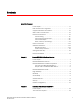
D Port Numbering Template 1 5 2 3 . 1 2 3 4 1 2 3 4 1 2 Port 61 LED Port 29 LED FC ports 32-63 (bottom to top) FC ports 0-31 (bottom to top) FC8-64 port blade 3 1 7 Blade Power LED Blade Status LED FC ports 24-31 Port and trunking group map 5 4 6 5 6 7 FC ports 16-23 FC ports 0-7 FC ports 8-15 FC8-32E port blade 2 3 1 4 Blade Power LED Blade Status LED FIGURE 39 140 5 6 7 8 2 FIGURE 38 . 8 4 Blade Status LED Blade Power LED Port 63 Port 30 FIGURE 37 .
Port Numbering Template . 1 2 3 4 2 3 1 7 . 1 2 5 4 6 Blade Power LED Blade Status LED FC ports 24-31 Port and trunking group map FIGURE 40 5 6 7 FC ports 16-23 FC ports 0-7 FC ports 8-15 FC16-32 port blade 2 3 1 4 Blade Power LED Blade Status LED FIGURE 41 D 3 4 FC ports 24-47 FC ports 0-23 FC16-48 port blade . 1 .
D Port Numbering Template 3 7 2 6 1 2 3 4 10 GbE ports 0-1 1 GbE ports 0-3 1 GbE ports 4-9 FC ports 6-11 FIGURE 43 142 4 1 5 5 6 7 FC ports 0-5 Blade Power LED Blade Status LED FX8-24 extension blade Brocade DCX 8510-4 Backbone Hardware Reference Manual 53-1002177-05
Index Numerics C 10 GbE ports, 130 cable management fingers, replacing, 61 cables attach SFP, 32 for FC8-64, 120 ICL, 35 managing, 35 QSFP, 88, 89 cables, ICL, 21 cables, managing, 19 Canadian requirement, 123 CE statement, 123 certifications, 109 chassis door, replacing, 60 chassis hardware components, 2 chassis name, customizing, 28 chassis, replacing, 94 chassisName command, 28 China RoHS, 124 classes of service, 109 A airflow, requirement, 114 altitude, requirement, 113 ambient temperature, require
command chassisName, 28 configShow, 36 configUpload, 36 configUpload -vf, 36 configure, 29, 31 date, 29 fabricShow, 29, 33, 36 frureplace, 83 ipaddrSet, 26 ipaddrSet -chassis, 26 ipaddrSet -cp0, 27 ipaddrSet -cp1, 27 ipAddrShow, 26, 36 licenseIdShow, 32 licenseShow, 32, 36 logout, 27 switchDisable, 29 switchEnable, 29 switchName, 28 switchShow, 33, 36 switchShow -qsfp, 34 sysShutdown, 36 tsClockServer, 31 tsTimeZone, 30 usbStorage, 36 compliance standards, 123 compliance, environmental regulation, 124 compl
Fibre Channel port specifications, 114 Fibre Channel Association, xix Fibre Channel Routing Services, 130 field replaceable units See FRU field-replaceable units See FRUs filler panel, replacing, 65 firmwaredownload from USB, 74 frame size, maximum, 110 frureplace command, 83 FRUs application blade replacing, 62 blades, weights, 112 blower assembly, 54 LEDs, 55 replacing, 80 cable management fingers, replacing, 61 chassis replacing, 94 chassis door replacing, 60 CP blade LEDs, 50 replacing, 66 CR blade LEDs
latency port to port, 110 switch, 110 LEDs blower assembly, 55 CP blade, 50 CR blade, 52 port blade, 48 power supply, 54 troubleshooting, 137 license, chassis software, 32 licenseIdShow command, 32 licenseShow command, 32 local time, synchronizing, 31 logout command, 27 M manageability, network, 11 managing cables, 35 media types, 111 N notices, safety, 121 NTP server, external, 31 numbering, port, 18 P PID mode, 31 port Fibre Channel, 110 numbering, 18 numbering template, 139 types, 111 port blade deter
safety notices, 121 security, 10 serial connection establishing, 24 troubleshooting, 136 serial port logout, 27 serviceability, features, 9 setting time zone, 30 SFPs, 32 shock, requirement, 113 site planning, 15 size and weight, 111 software features, 9 specifications, general, 109 status application blade, 44 blower assembly, 54 core switch blade, 51 CP blade, 50 port blade, 44 power supply, 53 WWN card, 55 status, port blade, 44 switch connect to, 25 date and time, 29 domain ID, 29 switch latency, 110 sw
148 Brocade DCX 8510-4 Backbone Hardware Reference Manual 53-1002177-05