WWW.BROAN-NUTONE.
Safety . . . . . . . . . . . . . . . . . . . . . . . . . . . . . . . . . 3-4 Operation . . . . . . . . . . . . . . . . . . . . . . . . . . . . . . . .5 Cleaning and Maintenance . . . . . . . . . . . . . . . . . .6 Motor Grease Filter(s) Non-Ducted Recirculation Filter(s) Fan Blade Stainless Steel Cleaning Painted Finish Cleaning Installation . . . . . . . . . . . . . . . . . . . . . . . . . . . . 7-20 INSTALLATION MANUAL TABLE OF CONTENTS Recommended Tools and Accessories for Installation . . . . . . .
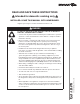
READ AND SAVE THESE INSTRUCTIONS ! Intended for domestic cooking only ! INSTALLER: LEAVE THIS MANUAL WITH HOMEOWNER. Register your range hood online at www.broan-nutone.com ! WARNING TO REDUCE THE RISK OF FIRE, ELECTRIC SHOCK, OR INJURY TO PERSONS, OBSERVE THE FOLLOWING: • Use this unit only in the manner intended by the manufacturer. If you have questions, contact the manufacturer at the address or telephone number listed in the warranty.
! WARNING TO REDUCE THE RISK OF A RANGE TOP GREASE FIRE: a) Never leave surface units unattended at high settings. Boilovers cause smoking and greasy spillovers that may ignite. Heat oils slowly on low or medium settings. b) Always turn hood ON when cooking at high heat or when flambeing food (i.e.: Crêpes Suzette, Cherries Jubilee, Peppercorn Beef Flambé). c) Clean ventilating fan frequently. Grease should not be allowed to accumulate on fan, filters or in exhaust ducts. d) Use proper pan size.
Operation Always turn your hood on before you begin cooking to establish an air flow in the kitchen. Let the blower run for a few minutes to clear the air after you turn off the range. This will help keep the whole kitchen cleaner and fresher. Operate the hood as follows: TEN2 SERIES BLOWER BUTTON When blower is OFF, press this button to turn ON the blower at the last saved speed. If there was no speed saved, the blower will be set on LOW speed.
Cleaning and Maintenance Proper maintenance of the Range Hood will assure proper performance of the unit. MOTOR The motor is permanently lubricated and never needs oiling. If the motor bearings make excessive or unusual noise, replace the motor with the exact service motor. The fan blade should also be replaced. GREASE FILTER(S) Grease filters should be cleaned frequently. Use a warm dishwashing detergent solution. Grease filters are dishwasher safe.
For ADA compliance installation guidelines, please visit www.broan-nutone.com Recommended Tools and Accessories for Installation • • • • • • • • • • • • • • • Measuring tape Phillips screwdriver no.
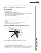
Contents Before proceeding to the installation, check the contents of the box. If items are missing or damaged, contact the manufacturer. Make sure that the following items are included: TEN2 Series TEN1 Series * FIND INSIDE OF HOOD (1) 3¼” X 10” DAMPER ASSEMBLY* (2) GREASE FILTERS (1) 7” ROUND DUCT CONNECTOR (1) GREASE FILTER * FIND INSIDE EZ1 COMPONENTS Use this template for marking; do not attempt to cut out the ducting hole through it.
Prepare the Hood 1 ] If present, remove all protective polyfilm from the hood and/or parts. 2 ] Using the finger cup or tab, remove the grease filter from the hood by pushing down and tilting filter(s) out . B B C C 3 ] Remove the EZ1 brackets from inside the hood by cutting off the tie wrap (no EZ1 brackets for TEN1 Series). Remove both screws holding damper assembly to hood. Remove parts bag (captured behind the damper assembly).
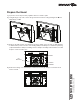
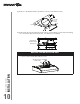
5 ] Remove 7” Round Duct Plate from top/back of hood (see illustration below). 7” ROUND DUCT PLATE 2 SCREWS 6 ] Remove Electrical Power Cable Knockout from top (vertical wiring) or back (horizontal wiring) of hood. Install an appropriate strain relief, 1/2” diameter (not included). ELECTRICAL POWER CABLE KNOCKOUT NON-DUCTED INSTALLATION ONLY 7 ] Remove 3 screws retaining the recirculation cover plate (shaded part in illustration below) to the hood. Discard this plate with its screws.
DUCTED INSTALLATION ONLY 8 ] Remove 3¼” x 10” vertical, 3¼” x 10” horizontal, or 7-inch round knockout plate as appropriate for your ducting method (see FIGURES 1 A and 1 B).
Prepare the Hood Location NOTE: Before starting installation, read all the steps of these instructions. Use the illustration below to identify your kitchen cabinet type. FRAMED CABINET FRAMELESS CABINET This manual covers 2 kinds of installation: the standard (without EZ1 brackets) and the EZ1 one-person installation system (using included template and brackets). Note that the EZ1 oneperson installation system is not available for TEN1 Series. For the standard installation, go to page 17.
4 ] Drill a 1/8” dia. pilot hole for house wiring, at A location on template. 5 ] Use a sharp pencil or 1/8” drill bit to mark the locations for the appropriate duct access holes (16 locations for 7” round duct, or 4 corner locations for rectangular duct). Remove the template. 6 ] Draw the border for the exhaust ducting by linking its marks (16 for round duct and 4 for rectangular duct), then cut the opening in the cabinet bottom (vertical exhaust) or in the wall (horizontal exhaust).
FRAMELESS CABINET Refer to the marking on brackets to determine the correct installation side and orientation. X Y Z 3X [ \ INSTALLATION MANUAL INSTALLATION 7/64” 14 Align the corresponding bracket to the cabinet side, while placing rear end of bracket against the wall. Draw a line on the outer edge of the bracket (as shown). Slide the bracket towards the center of cabinet and align the outside edge of the bracket with the marked line, keeping the rear end edge leaning on the wall.
Install the Hood (EZ1 Bracket) (TEN2 Series only) NOTE: The following procedure applies to both framed or frameless cabinet installations. 1 ] Run house power cable between service panel and hood location. 2 ] There are 2 pairs of recessed holes on each side of the top of the hood (on rear: A and B, on front C and D on illustration below); these holes allow the range hood to hang on the brackets (previously installed).
7 ] For framed cabinet, secure the hood to the EZ1 brackets using 4 no. 8-18 x 1/2” metal screws (included in parts bag). Insert 2 screws per side, in the slots (as shown in insets on illustration below). 8 ] For frameless cabinet, secure the hood to the cabinet using 4 no. 8 x 5/8” round head wood screws (included in parts bag). Insert 2 screws per side, in the slots (as shown in insets on illustration below).
Standard Installation (without EZ1 brackets) 1 ] Use the proper diagram below for placement of ductwork and electrical cutout in cabinet or wall. For a non-ducted installation, DO NOT cut a duct access hole, only cut the hole for electrical wiring.
Install the Hood (Standard installation) 1 ] Run house power cable between service panel and hood location. Run the house power cable into the hood through the strain relief previously installed in step 6 on page 10. 2 ] Hang hood from 4 mounting screws previously installed. Slide hood back towards wall until mounting screw heads are engaged in narrow end of keyhole slots in top of hood. While holding the hood, tighten screws securely. Attach power cable to the hood using the strain relief.
Connect the Wiring ! WARNING Risk of electric shock. Electrical wiring must be done by qualified personnel in accordance with all applicable codes and standards. Before connecting wires, switch power off at service panel and lock service disconnecting means to prevent power from being switched on accidentally. MOTOR GROUND WIRE GROUND SCREW HOUSE POWER CABLE 1 ] Connect House Power Cable to range hood wiring: BLACK to BLACK, WHITE to WHITE and GREEN or bare wire under GREEN ground screw.
Light Bulbs (TEN1 Series only) The TEN1 Series range hoods require two shielded Halogen Bulbs (120 V, 50 W max., MR16 or PAR16 with GU10 base) (not included). ! WARNING Do not touch lamps during or soon after operation. Burns may occur. In order to prevent the risk of personal injury, only install shielded halogen lamps. Also, never install a cool beam, a dichroic lamp, a lamp not suitable for use in recessed luminaires or identified for use in enclosed fixtures.
TEN2 SERIES 1 2 3 4 5 6 COLOR CODE BK BL BN BN/W J6 Override BLACK BLUE BROWN BROWN/WHITE G/Y O R W GREEN/YELLOW ORANGE RED WHITE LED J10 User interface mounted to J10 on back of control board.
TEN2 SERIES KEY NO.
TEN1 SERIES KEY NO. PART NO.
WARRANTY INSTALLATION MANUAL 24 Limited Warranty Warranty Period and Exclusions: Broan-NuTone LLC (either being the “Company”) warrants to the original consumer purchaser of its product (“you”) that the product (the “Product”) will be free from material defects in the Product or its workmanship for a period of one (1) year from the date of original purchase (or such longer period as may be required by applicable law).
WWW.BROAN-NUTONE.
Seguridad . . . . . . . . . . . . . . . . . . . . . . . . . . . . . . 3-4 Funcionamiento . . . . . . . . . . . . . . . . . . . . . . . . . . .5 Limpieza y mantenimiento . . . . . . . . . . . . . . . . . .6 Motor Filtro(s) de grasa Filtro(s) de recirculación Hélice Limpieza del acero inoxidable Limpieza de acabados pintados Instalación . . . . . . . . . . . . . . . . . . . . . . . . . . . . 7-20 Herramientas y accesorios recomendados para la instalación . . . . . . . . . . . . . . . . . . . . . . .
LEA ESTAS INSTRUCCIONNES Y GUÁRDELAS ! Exclusivamente para cocinas domésticas ! INSTALADOR: ENTREGUE ESTE MANUAL AL PROPIETARIO. Registre su campana de cocina en línea en www.broan-nutone.com ! ADVERTENCIA PARA REDUCIR EL RIESGO DE INCENDIO, DESCARGA ELÉCTRICA O LESIÓN CORPORAL, RESPETE LAS SIGUIENTES INDICACIONE: • Utilice esta unidad únicamente de la forma en que indica el fabricante.
! ADVERTENCIA PARA REDUCIR EL RIESGO DE QUE ARDA LA GRASA EN LA PARTE SUPERIOR DE LA COCINA: a) b) c) d) No deje nunca recipientes de cocina a fuego vivo sin vigilancia. Los desbordamientos producen humo y derrames grasientos que pueden inflamarse. Caliente el aceite despacio, a fuego lento o mediano. Ponga en marcha siempre la campana extractora al cocinar a temperaturas elevadas o al cocinar alimentos flameados (crepas Suzette, cerezas jubilee, res con pimienta flambeada).
Funcionamiento Ponga la campana en marcha siempre antes de empezar a cocinar para crear una corriente de aire en la cocina. Deje funcionar el ventilador impelente varios minutos para limpiar el aire cuando ya haya apagado la cocina. De este modo, la cocina estará más limpia y despejada. La campana funciona así: SERIE TEN2 BOTÓN DEL VENTILADOR Cuando el ventilador impelente esté APAGADO, presione este botón para ENCENDER el ventilador impelente en la última velocidad guardada.
Limpieza y mantenimiento El mantenimiento adecuado de la campana permitirá que funcione correctamente. MOTOR El motor está lubricado permanentemente y no necesita engrase nunca. Si los rodamientos del motor hacen un ruido excesivo o no habitual, sustituya el motor por otro idéntico. También se debería sustituir la hélice. FILTRO(S) DE GRASA Los filtros de grasa deberían limpiarse con frecuencia. Use una disolución de agua tibia y detergente para vajilla.
Para las directrices de instalación conforme a la ADA, visite www.broan-nutone.com Herramientas y accesorios recomendados para la instalación • • • • • • • • • • • • • • • Cinta métrica Destornillador Phillips n.
Contenido Antes empezar la instalación, verifique el contenido de la caja. Si faltan elementos o hay elementos dañados, póngase en contacto con el fabricante.
Prepare la campana 1 ] De haberla, retire de la campana y de todas las piezas la película protectora. 2 ] Use el orificio de agarre para retirar de la campana los filtros de grasa empujando hacia abajo e inclinando los filtros hacia fuera . B B C C 3 ] Retire los soportes EZ1 del interior de la campana cortando la tira de amarre (no hay soportes EZ1 en la campana de serie TEN1). Retire ambos tornillos que sujetan el conjunto de la clapeta a la campana.
5 ] Retire la placa para conducto redondo de 7” de la parte superior trasera de la campana (véase la ilustración de abajo. PLACA PARA CONDUCTO REDONDO DE 7” 2 TORNILLOS 6 ] Retire la parte punzonada para el cable de alimentación eléctrica desde la parte superior (cableado vertical) o desde la parte trasera (cableado horizontal) de la campana. Instale una descarga de presión adecuada de 1/2” de diámetro (no incluida).
INSTALACIÓN CON CONDUCTOS ÚNICAMENTE 8 ] Retire la placa punzonada vertical de 3¼” x 10”, la placa punzonada horizontal de 3¼” x 10” o la placa punzonada redonda de 7 pulgadas, según el modo de evacuación elegido (véanse las Figuras 1 A y 1 B).
Prepare la ubicación de la campana NOTA: antes de empezar la instalación, lea todas las etapas de estas instrucciones. Use la ilustración de abajo para reconocer su tipo de armario de cocina. ARMARIO CON ARMAZÓN ARMARIO SIN ARMAZÓN Este manual cubre 2 tipos de instalación: la normal (sin soportes EZ1) y la instalación EZ1 por una persona (usando la plantilla y los soporte provistos). Tenga en cuenta que el sistema de instalación EZ1 por una persona no está disponible para la serie TEN1.
4 ] Taladre un orificio piloto de 1/8” de diámetro para el cableado de la vivienda, en el punto A de la plantilla. 5 ] Use un lápiz afilado o una broca de 1/8” para marcar los puntos para los orificios de acceso de los conductos (16 puntos para un conducto redondo de 7”, o 4 puntos en las esquinas para un conducto rectangular). Retire la plantilla.
ARMARIO SIN ARMAZÓN Consulte las marcas de los soporte para establecer el lado y la orientación correctos de la instalación (marcas en ingles solamente: front = frente, left = izquierda, lean on rear wall = appoyar contra la pared de atrás). X Y Z 3X [ \ 7/64” MANUAL DE INSTALACIÓN INSTALACIÓN Alinee el soporte correspondiente al lado del armario, colocando al mismo tiempo la 14 parte trasera del soporte contra la pared.
Instale la campana (Soporte EZ1) (serie TEN2 únicamente) NOTA: El procedimiento siguiente se aplica a las instalaciones en armarios con armazón y sin armazón. 1 ] Lleve el cable de alimentación de la vivienda del tablero de servicio al lugar de la campana.
7 ] En los armarios con armazón, sujete la campana a los soportes EZ1 por medio de los (4) tornillos para metal no 8-18 x 1/2” (los tornillos vienen en la bolsa de piezas). Introduzca (2) tornillos en cada lado, en las ranuras (como se ve en los detalles de la ilustración de abajo). 8 ] En los armarios sin armazón, sujete la campana al armario por medio de los (4) tornillos de cabeza redonda para madera no 8 x 5/8” (los tornillos vienen en la bolsa de piezas).
Instalación normal (sin soportes EZ1) 1 ] Use el diagrama adecuado de abajo para colocar los conductos y la alimentación eléctrica en el armario o en la pared. Para una instalación sin conductos, NO corte el orificio de acceso al conducto; corte sólo el orificio para el cableado eléctrico.
Instale la campana (Instalación normal) 1 ] Lleve el cable de alimentación de la vivienda del tablero de servicio al lugar de la campana. Lleve el cable de alimentación de la vivienda a la campana a través de la descarga de presión instalada previamente en la etapa 6 en la página 10. 2 ] Cuelgue la campana de los cuatro (4) tornillos de montaje instalados previamente.
Conecte el cableado ! ADVERTENCIA Riesgo de descarga eléctrica. El cableado eléctrico debe hacerlo personal cualificado de acuerdo con los códigos y normas aplicables. Antes de conectar los hilos, corte la corriente en el tablero de servicio y bloquee éste para evitar que se ponga en marcha accidentalmente.
Instale las bombillas (Serie TEN1 solamente) Instale dos bombillas halógenas con pantalla (120 V, 50 W máx., MR16 o PAR16 con base GU10) (no incluido). ! ADVERTENCIA No toque las bombillas mientras funcionen o poco después de que hayan dejado de funcionar. Podría quemarse. Para prevenir riesgos de daños personales, instale sólo bombillas halógenas con pantalla. Asimismo, no instale nunca una bombilla de haz frío, dicróica o no adecuada para luces encastradas o pensada sólo para lámparas cerradas.
SERIE TEN2 1 2 3 4 5 6 CÓDIGO DE COLORES AZ B C C/B J6 Interruptor de anulación AZUL BLANCO CAFÉ CAFÉ/BLANCO NA NE R V/AM NARANJA NEGRO ROJO VERDE/AMARILLO LED J10 Interfaz de usuario conectado en J10 en la parte trasera de la placa electrónica Interfaz 8 7 6 5 LED J4 NE 1 2 3 4 B R LED 4 3 2 1 R J1 Transformador J2 5 4 3 2 1 Potencia, Motor R 7 6 5 4 3 2 1 AZ AZ NE B NE MOTOR DEL VENTILADOR Placa electrónica 6 5 4 3 2 1 R (Baja) 120 V CA NA (Media) Línea NE (Alta) NE Neutr
SERIE TEN2 PIEZAS DE REPUESTO MANUAL DE INSTALACIÓN CANTIDAD BLANCA NEGRA ACERO INOX. 30” 36” 30” 36” 30” 36” 42” 1 1 S97020029 PLACA DE CUBIERTA DE RECIRCULACIÓN, NEGRA (INCLUYE TORNILLOS) S97020030 PLACA DE CUBIERTA DE RECIRCULACIÓN, BLANCA (INCLUYE TORNILLOS) 1 1 1 S97020031 PLACA DE CUBIERTA DE RECIRCULACIÓN, ACERO INOX.
SERIE TEN1 N.o N.º PIEZA DESCRIPCIÓN BLANCA CANTIDAD ACERO INOX. NEGRA 30” 36” 30” 36” 30” 36” 2 3 4 5 6 7 8 * * * * 1 1 1 1 1 1 1 1 1 1 1 1 1 1 1 1 1 1 1 1 1 1 1 1 1 1 1 1 1 1 1 1 1 1 1 1 1 1 1 1 1 1 1 1 1 1 1 1 1 1 1 1 1 1 1 1 1 1 1 1 2 1 1 2 1 1 2 1 1 2 1 1 2 1 1 2 1 * ÍTEM NO MOSTRADO. REPUESTOS Y REPARACIONES Para que el aparato esté en buenas condiciones, use sólo repuestos genuinos Broan-NuTone LLC.
GARANTÍA MANUAL DE INSTALACIÓN 24 Garantía limitada Periodo y exclusiones de la garantía: Broan-NuTone LLC (sea esta la “Compañía”) garantiza al consumidor comprador original de su producto (“usted”) que el producto (el “Producto”) estará libre de defectos en materiales o en mano de obra, por un periodo de un (1) año a partir de la fecha de compra original (o por un periodo mayor según sea requerido por la legislación aplicable).