WWW.BROAN.COM WWW.BROAN.
Safety . . . . . . . . . . . . . . . . . . . . . . . . . . . . . . . . . 3-4 Operation . . . . . . . . . . . . . . . . . . . . . . . . . . . . . . . 5 Cleaning and Maintenance . . . . . . . . . . . . . . . . . 6 Motors Grease Filters Non-Ducted Recirculation Filters Fan Wheels Stainless Steel Cleaning Installation . . . . . . . . . . . . . . . . . . . . . . . . . . . . 7-22 Recommended Tools and Accessories for Installation . . . . . . . . . . . . Install Ductwork (Ducted Installations Only) . . .
READ AND SAVE THESE INSTRUCTIONS ! Intended for domestic cooking only ! INSTALLER: LEAVE THIS MANUAL WITH HOMEOWNER. For Broan Elite products in U.S.A., register your range hood online at www.broan.com For Broan Elite products in Canada, register your range hood online at www.broan.ca ! WARNING TO REDUCE THE RISK OF FIRE, ELECTRIC SHOCK, OR INJURY TO PERSONS, OBSERVE THE FOLLOWING: • Use this unit only in the manner intended by the manufacturer.
! WARNING TO REDUCE THE RISK OF A RANGE TOP GREASE FIRE: a) Never leave surface units unattended at high settings. Boilovers cause smoking and greasy spillovers that may ignite. Heat oils slowly on low or medium settings. b) Always turn hood ON when cooking at high heat or when flambeing food (i.e.: Crêpes Suzette, Cherries Jubilee, Peppercorn Beef Flambé). c) Clean ventilating fan frequently. Grease should not be allowed to accumulate on fan, filters or in exhaust ducts. d) Use proper pan size.
Operation Always turn your hood on before you begin cooking to establish an air flow in the kitchen. Let the blower run for a few minutes to clear the air after you turn off the range. This will help keep the whole kitchen cleaner and fresher. Operate the hood as follows: BLOWER BUTTON When blower is OFF, press this button to turn ON the blower at the last saved speed. If there was no speed saved, the blower will be set on LOW speed.
Cleaning and Maintenance Proper maintenance of the Range Hood will assure proper performance of the unit. MOTORS The motors are permanently lubricated and never need oiling. If the motor bearings make excessive or unusual noise, replace the motor with the exact service motor. The fan wheel should also be replaced. GREASE FILTERS The grease filters should be cleaned frequently. Use a warm dishwashing detergent solution. Grease filters are dishwasher safe.
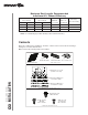
For ADA compliance installation guidelines, please type the model number into our website. Recommended Tools and Accessories for Installation • • • • • • • • • • • • • • • Measuring tape Phillips screwdriver no.
Maximum Duct Lengths Recommended to Achieve 80% Exhaust Efficiency HORIZONTAL MAXIMUM DUCT LENGTHS VERTICAL MAXIMUM DUCT LENGTHS 3¼” X 10” 3¼” X 14” 3¼” X 10” 3¼” X 14” 7” ROUND MAXIMUM DUCT LENGTH ROOF OR WALL CAP WITH DAMPER ELBOW(S)* (90° AND/OR 45°) 44 ft. 76 ft. 39 ft. 72 ft. 89 ft. 1 0 35 ft. 66 ft. 30 ft. 62 ft. 79 ft. 1 1 26 ft. 56 ft. 22 ft. 52 ft. 70 ft. 1 2 * Standard elbows with 1” internal radius.
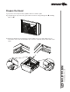
Prepare the Hood 1 ] If present, remove all protective polyfilm from the hood and/or parts. 2 ] Using the finger cup, remove the grease filters from the hood by pushing down and tilting filters out . B C 3 ] Remove both fillers by removing the 3 screws holding each one of them. Slide each one towards the center of the hood and tilt it up to remove it completely. Set the fillers and screws aside.
4 ] Remove the screw holding the 3¼” x 10” adapter/damper as well as the one for the 3¼” x 14” adapter/damper, remove their tape strips and and put the adapter/dampers aside. Save these screws, they will be used later to hold the blower cover plate. 5 ] Remove both tape strips holding the 7” round adapter, and put the adapter aside. 6 ] Remove the parts bag taped in the lower left corner of the hood.
8 ] Remove the EZ1 brackets from inside the hood by cutting off the tie wrap. Discard the tie wrap. EZ1 BRACKETS 9 ] Remove Electrical Power Cable Knockout from top (vertical exhaust) or back (horizontal exhaust) of hood. For knockout removed from back of hood, install an appropriate strain relief, 1/2” diameter (not included). For knockout removed from top of hood, the strain relief will be installed later.
3¼” x 14” DUCTED INSTALLATION ONLY 12 ] Remove 3¼” x 14” vertical or 3¼” x 14” horizontal knockout plate as appropriate for your ducting method (see FIGURES 1 A and 1 B). FIGURE 1 B FIGURE 1 A 3¼” X 14” VERTICAL KNOCKOUT PLATE 3¼” X 14” HORIZONTAL KNOCKOUT PLATE FIGURE 2 13 ] Using the screws located on top of the hood (FIGURE 2), attach the 3¼” x 14” Damper Assembly on top OR back of hood (see FIGURE 3 A below) over the knockout opening.
3¼” x 10” OR 7” ROUND DUCTED INSTALLATION ONLY 12 ] Remove 3¼” x 10” vertical, 3¼” x 10” horizontal (both are the rectangular central knockout plates, see hatched areas) or 7-inch round knockout plate as appropriate for your ducting method (see FIGURES 1 A and 1 B).
Prepare the Hood Location NOTE: Before starting installation, read all the steps of these instructions. Use the illustration below to identify your kitchen cabinet type. FRAMED CABINET FRAMELESS CABINET This manual covers 2 kinds of installation: the standard (without EZ1 brackets) and the EZ1 one-person installation system (using included template and brackets). For the standard installation, go to page 19.
4 ] Drill a 1/8” dia. pilot hole for house wiring, at B location on template. 5 ] Use a sharp pencil or 1/8” drill bit to mark the locations for the appropriate duct access holes (16 locations for 7” round duct, or 4 corner locations for rectangular duct). Remove the template. 6 ] Draw the border for the exhaust ducting by linking its marks (16 for round duct and 4 for rectangular duct), then cut the opening in the cabinet bottom (vertical exhaust) or in the wall (horizontal exhaust).
FRAMELESS CABINET Refer to the marking on brackets to determine the correct installation side and orientation. X Y Z 3X [ \ INSTALLATION MANUAL INSTALLATION 7/64” 16 Align the corresponding bracket to the cabinet side, while placing rear end of bracket against the wall. Draw a line on the outer edge of the bracket (as shown). Slide the bracket towards the center of cabinet and align outside edge of the bracket to marked line, keeping the rear end edge leaning on the wall.
Install the Hood (EZ1 Bracket) NOTE: The following procedure applies to both frame or frameless cabinet installations. 1 ] Run house power cable between service panel and hood location. 2 ] There are 2 pairs of recessed holes on each side of the top of the hood (on rear: A and B, on front C and D on illustration below); these holes allow the range hood to hang on the brackets (previously installed).
7 ] For framed cabinet, secure the hood to the EZ1 brackets using a 10” screwdriver bit and 4 no. 8-18 x 1/2” metal screws (included in parts bag). Insert 2 screws per side, in the slots (as shown in inset on illustration below). 8 ] For frameless cabinet, secure the hood to the cabinet using a 10” screwdriver bit and 4 no. 8 x 5/8” round head wood screws (included in parts bag). Insert 2 screws per side, in the slots (as shown in inset on illustration below).
Standard Installation (without EZ1 brackets) 1 ] Use the proper diagram below for placement of ductwork and electrical cutout in cabinet or wall. For a non-ducted installation, DO NOT cut a duct access hole, only cut the hole for electrical wiring.
Install the Hood (Standard Installation) NOTE: Two installers are recommended because of the weight of this hood. 1 ] Run house power cable between service panel and hood location. For hood with power cable access located on back of hood, run the house power cable into the hood through the strain relief previously installed in step 9 on page 11. For hood with power cable access located on top, tighten the strain relief to the power cable before inserting the strain relief in the knockout hole.
Connect the Wiring ! WARNING Risk of electric shock. Electrical wiring must be done by qualified personnel in accordance with all applicable codes and standards. Before connecting wires, switch power off at service panel and lock service disconnecting means to prevent power from being switched on accidentally. MOTORS GROUND WIRE GROUND SCREW HOUSE POWER CABLE 1 ] Connect House Power Cable to range hood wiring: BLACK to BLACK, WHITE to WHITE and GREEN or bare wire under GREEN ground screw.
Install the Filters Ducted Installation Only: Re-install grease filters removed in step 2 , page 9, under “Prepare the Hood”. INSTALLATION MANUAL INSTALLATION Non-ducted Installation Only: Purchase two non-ducted filters from your local distributor or retailer (see product specification label for filter type). Attach the non-ducted filters following instructions packed with the nonducted filters.
Control Board Line 120 VAC Neutral Supply Ground User interface mounted on back side of control board ADA Override J6 1 2 3 4 5 6 J1 BK Transformer J2 R 1 4 3 2 7 6 5 2 1 5 4 3 G/Y W BK 24 V Class 2 BK W BK (High) O (Medium) R (Low) BK BL BL BL R R Heatshrink W W BK BL BN BN/W G/Y 2 1 R (L) O (M) BK (H) G/Y W O (M) BK (H) G/Y W R (L) R BK O R W Y 1 2 ORANGE RED WHITE YELLOW 6 5 4 3 2 1 6 5 4 3 2 1 W O BK G/Y R W O BK G/Y R BK W R Low speed capacitor REF: 990729
SPE1 SERIES C B O D N L E M F G K H I KEY NO. 1 2 3 4 5 6 7 8 PART NO.
INSTALLATION MANUAL WARRANTY Limited Warranty Warranty Period and Exclusions: Broan-NuTone LLC andVenmarVentilation ULC (either being the “Company”) warrants to the original consumer purchaser of its product (“you”) that the product (the “Product”) will be free from material defects in the Product or its workmanship for a period of one (1) year from the date of original purchase (or such longer period as may be required by applicable law).
WWW.BROAN.COM WWW.BROAN.
Seguridad . . . . . . . . . . . . . . . . . . . . . . . . . . . . . . 3-4 Funcionamiento . . . . . . . . . . . . . . . . . . . . . . . . . . 5 Limpieza y mantenimiento . . . . . . . . . . . . . . . . . 6 Motores Filtros de grasa Filtros de recirculación Ruedas del ventiladores Limpieza del acero inoxidable Instalación . . . . . . . . . . . . . . . . . . . . . . . . . . . . 7-22 Herramientas y accesorios recomendados para la instalación . . . . . . . . . . . . . . . . . . . . . . .
LEA ESTAS INSTRUCCIONNES Y GUÁRDELAS ! Exclusivamente para cocinas domésticas ! INSTALADOR: ENTREGUE ESTE MANUAL AL PROPIETARIO. En EE.UU., registre su Broan Elite campana de cocina en línea en www.broan.com En Canadá, registre su Broan Elite campana de cocina en línea en www.broan.ca ! ADVERTENCIA PARA REDUCIR EL RIESGO DE INCENDIO, DESCARGA ELÉCTRICA O LESIÓN CORPORAL, RESPETE LAS SIGUIENTES INDICACIONE: • Utilice esta unidad únicamente de la forma en que indica el fabricante.
! ADVERTENCIA PARA REDUCIR EL RIESGO DE QUE ARDA LA GRASA EN LA PARTE SUPERIOR DE LA COCINA: a) b) c) d) No deje nunca recipientes de cocina a fuego vivo sin vigilancia. Los desbordamientos producen humo y derrames grasientos que pueden inflamarse. Caliente el aceite despacio, a fuego lento o mediano. Ponga en marcha siempre la campana extractora al cocinar a temperaturas elevadas o al cocinar alimentos flameados (crepas Suzette, cerezas jubilee, res con pimienta flambeada).
Funcionamiento Ponga la campana en marcha siempre antes de empezar a cocinar para crear una corriente de aire en la cocina. Deje funcionar el ventilador impelente varios minutos para limpiar el aire cuando ya haya apagado la cocina. De este modo, la cocina estará más limpia y despejada. Utilice la campana de la siguiente manera: BOTÓN DEL VENTILADOR Cuando el ventilador impelente esté APAGADO, presione este botón para ENCENDER el ventilador impelente en la última velocidad guardada.
Limpieza y mantenimiento El mantenimiento adecuado de la campana permitirá que funcione correctamente. MOTORES Los motores estan lubricados permanentemente y no necesitan engrase nunca. Si los rodamientos de uno motor hacen un ruido excesivo o no habitual, sustituya este motor por otro idéntico. También se debería sustituir su rueda del ventilador. FILTROS DE GRASA Los filtros de grasa deberían limpiarse con frecuencia. Use una disolución de agua tibia y detergente para vajilla.
Para las directrices de instalación conforme a la ADA, por favor, ingrese su número de modelo en nuestro sitio web. Herramientas y accesorios recomendados para la instalación • • • • • • • • • • • • • • • Cinta métrica Destornillador Phillips n.
Largos maximales recommandados de conducto para conseguir un rendimiento de 80% de evacuación de aire LARGOS MAXIMALES DE LARGOS MAXIMALES DE CONDUCTO HORIZONTAL CONDUCTO VERTICAL LARGO MÁXIMO DE CONDUCTO DE TAPA DE TECHO Ó DE PARED CON REGULADOR CODO(S)* DE (90° Y/Ó 45°) 3¼” X 10” 3¼” X 14” 3¼” X 10” 3¼” X 14” 7” DE DIÁMETRO 44 pies 76 pies 39 pies 72 pies 89 pies 1 0 35 pies 66 pies 30 pies 62 pies 79 pies 1 1 26 pies 56 pies 22 pies 52 pies 70 pies 1 2 DE TIRO * Codos es
Prepare la campana 1 ] De haberla, retire de la campana y de todas las piezas la película protectora. 2 ] Use el orificio de agarre para retirar de la campana los filtros de grasa empujando hacia abajo e inclinando los filtros hacia fuera . B C 3 ] Retire las piezas de relleno quitando los 3 tornillos que sujetan cada una de ellas. Desplace cada revestimiento hacia el centro de la campana e inclínelo hacia arriba para retirarlo completamente. Reserve las piezas de relleno y los tornillos.
4 ] Retire el tornillo que sujeta el adaptador/clapeta de retención de 3¼” x 10” y el tornillo que sujeta el adaptador/clapeta de retención de 3¼” x 14”, retire sus tira de cinta, y reserve los dos adaptador/clapeta de retención. Guarde estos tornillos ya que ellos volverán a usar después para sujetar la placa. 5 ] Retire las dos tiras de cinta que sujetan el adaptador redondo de 7” y reserve el adaptador. 6 ] Saque la bolsa de piezas sujeta con cinta en la esquina inferior izquierda de la campana.
8 ] Retire los soportes EZ1 del interior de la campana cortando la tira de amarre. Deseche la tira de amarre. SOPORTES EZ1 9 ] Retire la parte punzonada para el cable de alimentación eléctrica desde la parte superior (salida vertical) o desde la parte trasera (salida horizontal) de la campana. Para la parte punzonada quitado desde la parte trasera de la campana, instale una descarga de presión adecuada de 1/2” de diámetro (no incluida).
INSTALACIÓN CON CONDUCTOS DE 3¼" x 14" ÚNICAMENTE 12 ] Retire la placa punzonada vertical de 3¼” x 14” o horizontal de 3¼” x 14”, según el modo de evacuación elegido (véanse las FIGURAS 1 A y 1 B).
INST. CON CONDUCTOS DE 3¼” x 14” O 7” REDONDO ÚNICAMENTE 12 ] Retire la placa punzonada vertical de 3¼” x 10”, horizontal de 3¼” x 10” (ambos están las placas punzonadas rectangular centrales, veanse las zonas rayadas) o la placa punzonada redonda de 7 pulgadas, según el modo de evacuación elegido (véanse las FIGURAS 1 A y 1 B).
Prepare la ubicación de la campana NOTA: antes de empezar la instalación, lea todas las etapas de estas instrucciones. Use la ilustración de abajo para reconocer su tipo de armario de cocina. ARMARIO CON ARMAZÓN ARMARIO SIN ARMAZÓN Este manual cubre 2 tipos de instalación: la normal (sin soportes EZ1) y la instalación EZ1 por una persona (usando la plantilla y los soporte provistos). Para la instalación normal, vaya a la página 19.
4 ] Taladre un orificio piloto de 1/8” de diámetro para el cableado de la vivienda, en el punto B de la plantilla. 5 ] Use un lápiz afilado o una broca de 1/8” para marcar los puntos para los orificios de acceso de los conductos (16 puntos para un conducto redondo de 7”, o 4 puntos en las esquinas para un conducto rectangular). Retire la plantilla.
ARMARIO SIN ARMAZÓN Consulte las marcas de los soporte para establecer el lado y la orientación correctos de la instalación (marcas en inglés solamente: front = parte delantera, left = izquierda, lean on rear wall = apoyar contra la pared trasera). X Y Z 3X [ \ 7/64” MANUAL DE INSTALACIÓN INSTALACÍON Alinee el soporte correspondiente al lado del armario, colocando al mismo tiempo la 16 parte trasera del soporte contra la pared.
Instale la campana (Soporte EZ1) NOTA: El procedimiento siguiente se aplica a las instalaciones en armarios con armazón y sin armazón. 1 ] Lleve el cable de alimentación de la vivienda del tablero de servicio al lugar de la campana. 2 ] Hay 2 pares de orificios rebajados en cada lado de la parte superior de la campana (en la parte trasera: A y B, en la parte delantera C y D en la ilustración de abajo); estos orificios permiten colgar la campana a los soportes (instalados previamente).
7 ] En los armarios con armazón, sujete la campana a los soportes EZ1 por medio de los cuatro (4) tornillos para metal n.° 8-18 x 1/2” (los tornillos vienen en la bolsa de piezas) con un taladro de 10”. Introduzca dos (2) tornillos en cada lado, en las ranuras (como se ve en los detalles de la ilustración de abajo). 8 ] En los armarios sin armazón, sujete la campana al armario por medio de los cuatro (4) tornillos de cabeza redonda para madera n.
Instalación normal (sin soportes EZ1) 1 ] Use el diagrama adecuado de abajo para colocar los conductos y la alimentación eléctrica en el armario o en la pared. Para una instalación sin conductos, NO corte el orificio de acceso al conducto; corte sólo el orificio para el cableado eléctrico.
Instale la campana (Instalación normal) NOTA: Debido al peso de esta campana, se aconseja que la instalen dos instaladores. 1 ] Lleve el cable de alimentación de la vivienda del tablero de servicio al lugar de la campana. Si el orificio de acceso del cable alimentación de la campana este en su parte trasera, lleve el cable de alimentación de la vivienda a la campana a través de la descarga de presión instalada previamente en la etapa 9 en la página 11.
Conecte el cableado ! ADVERTENCIA Riesgo de descarga eléctrica. El cableado eléctrico debe hacerlo personal cualificado de acuerdo con los códigos y normas aplicables. Antes de conectar los hilos, corte la corriente en el tablero de servicio y bloquee éste para evitar que se ponga en marcha accidentalmente.
Instale los filtros Instalación con conductos únicamente: Vuelva a instalar los filtros de grasa que quitó en la etapa 2 , en la página 9 (sección “Prepare la campana”). MANUAL DE INSTALACIÓN INSTALACÍON Instalación sin conductos únicamente: Compre dos filtros para instalación sin conductos a un distribuidor o minorista local (vea la etiqueta de especificaciones del producto para el tipo de filtro). Instale los filtros sin conductos siguiendo las instrucciones que vienen con los filtros.
Placa electrónica Fuente de Línea energía Neutro 120 VCA Tierra Interfaz de usuario montada en la parte trasera de la placa electrónica.
SERIE SPE1 C B O D N L E M F G K H I CANTIDAD 30" 36" 1 S97020031 PLACA DE CUBIERTA DE RECIRCULACIÓN, ACERO INOX. (INCLUYE TORNILLOS) 1 1 2 SR680508 PLACA DE CONDUCTO REDONDO DE 7” (INCLUYE TORNILLOS) 1 1 3 S97020469 CONJUNTO DE CLAPETA DE 3¼” X 14” (INCLUYE TORNILLOS) 1 1 4 S97020534 CONJUNTO DE CLAPETA DE 3¼” X 10” (INCLUYE TORNILLOS) 1 1 2 2 5 S97021325 CONDENSADOR (INCLUYE TIRA DE AMARRE) 6 S97021328 MONTAJE DEL VENTILADOR ROTACIÓN A DERECHA (INCLUYE N.° 5, N.
MANUAL DE INSTALACIÓN GARANTÍA Garantía limitada Periodo y exclusiones de la garantía: Broan-NuTone LLC o Venmar Ventilation ULC (sea esta la “Compañía”) garantiza al consumidor comprador original de su producto (“usted”) que el producto (el “Producto”) estará libre de defectos en materiales o en mano de obra, por un periodo de un (1) año a partir de la fecha de compra original (o por un periodo mayor según sea requerido por la legislación aplicable).