
Installation

4
2. Installation (cont’d)
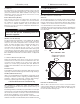
2.6 Exterior Hoods
It is important that the fresh air intake hood be positioned well away
from any source of contamination. The exterior supply and exhaust
hoods must be separated enough to prevent cross-contamination
and at an elevation that will prevent blockage by snow, dirt and
leaves.
NOTE:
Consult local building code for restrictions in your area.
A rodent screen with 1/4” mesh must be installed to prevent the
intake of large debris and animals. A backdraft damper may need
to be installed in the exhaust duct to prevent cold air entering the
building if the unit is to be shut off for a long period of time.
To maintain optimum airflow performance, exterior hood selection
must be such that the minimum free area of opening is 140 inches.
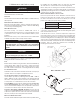
2.7 Drains
The drain fittings provided with the unit will accept a 3/4” NPT coupler
(supplied by others). The drain line for the unit must be fabricated
on-site and connected to the building main. A loop in the hose or
trap in the copper or plastic pipe must be provided to prevent sewer
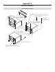
gases from entering the unit when connecting to a drain as illustrated
in Appendix D.
NOTE:
Consult local building code for plumbing requirements in your area.
If copper pipe is to be used, ensure not to solder to the 3/4” coupler
while it is attached to the plastic drain fitting as deformation may
occur. Ensure adequate slope is present to allow good drainage
(minimum 1/4” per foot).
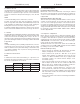
2.8 Electrical Connections
POWER
A terminal block and strain relief bushing or a junction box is
provided for line voltage to make the necessary power connections.
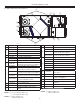
The electrical requirements are as follows:
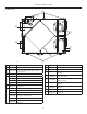
B6LC B1600705 B12LC
VOLTAGE 120 V 120 V 120 V
MCA 9.50 A 6.63 A 14.30 A
MOP 12.00 A 9.13 A 20.00 A
3. Controls
3.1 General Information
FAN INTERLOCK RELAY OUTPUT (FF)
External fan control can be achieved by connecting an external
24 volts fan control through dry contacts (FF). These contacts are
closed on a call for ventilation or defrost. See wiring diagram shown
in Appendix E.
S
PEED SELECTION (6LC /12LC UNITS ONLY)
There are three speed settings available with the controls, only two
of which can be functional at any one time. The units are factory
set to use the low and high speed taps on the blower motors. If
necessary, the medium speed tap can be used instead of the low
speed tap. See wiring diagrams for instructions on how to make this
change. Units without the remote wall control option can be shut off
by opening the contact between LOW - COM or HIGH - COM as
shown in Appendix E-2.
3.2 Sequence of Operation
Before start-up, check the unit for obstructive packaging, objects
near or in blowers, dampers, heat exchangers, etc. Once installation
is complete, check all modes of operation to ensure that the unit is
working properly. Close the doors and check for operation on LOW,
COM and HIGH. Use a wall control or the dry contact switching to
run fan speeds as shown in Appendix E-2.
The B1600705 unit is two speed. Low speed can be initiated by
creating a closure across LOW - COM or high speed can be initiated
by creating a closure across HIGH - COM.
UNIT CHECK POINTS (ALL UNITS):
• Power connected, no ventilation call - Both fans are off, defrost
damper (if equipped) closes off fresh air from outdoors.
• Power connected, low speed call - Both fans on low speed
internal defrost damper (if equipped) opens fresh air from
outdoors. For B6LC and B12LC units only, if equipped with
recirculation module, the internal defrost damper closes
recirculation opening.
• Power connected, high speed call - Both fans on high speed,
defrost damper opens fresh air from outside. For B6LC and
B12LC units only, if equipped with recirculation module, the
internal defrost damper closes recirculation opening.
• Power connected, occupied timer/sensor connection open
(unoccupied mode) - Both fans are off, defrost damper closes
fresh air from outdoors. For B6LC and B12LC units only, if equipped
with recirculation module, the internal defrost damper opens
recirculation opening.
• Power connected, FF control contacts close during unit ventilation
or defrost cycle.