
Manual

AP1 & RP SERIES
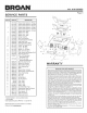
Page 4
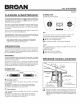
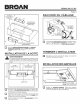
DAMPER /
DUCT
CONNECTOR
VERTICALDUCT
KNOCKOUT
/
i11 i/I
HORIZONTAL DUCT
•" KNOCKOUT
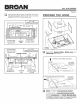
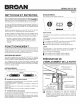
CONNECT THE WIRING
HOUSE
POWER
CABLE
GREEN
GROUND
SCREW
[_ Connect House Power Cable to hood wiring
range
- BLACK to BLACK, WHITE to WHITE, and GREEN or
BARE WIRE to GREEN Ground Screw.
3 Remove Vertical Duct Knockout or Horizontal Duct
Knockout and attach Damper / Duct Connector with
two (2) screws (supplied).
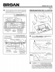
INSTALL THE HOOD
_ ARNING
To reduce the risk of electrical shock, switch power off
at service panel. Lock or tag service panel to prevent
power from being switched on accidentally.
COMPLETE INSTALLATION
Re-install the wiring cover, bottom cover, and filters that
were removed in Step 3.
m
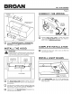
MOUNTING
SCREWS (4)
J
<t>
I
© HOUSE
POWER
CABLE
o !
,, //.,d
DUCTWORK
m
m
Run House Power Cable between service panel and
hood location. Attach power cable to hood using appropri-
ate connector.
Hold the hood in position under the cabinet. Make sure
the damper / duct connector enters the Ductwork and
that the damper opens and closes freely.
Tighten the four (4) Mountin,,q Screws completely to se-
cure the hood to the cabinet.
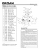
INSTALL LIGHT BULBS
t
(2) ROTATE
CLOCKWISE
[_ Install Halogen_ Bulbs. Use 120 V, 50 W, shielded halo-
gen bulbs - MR16 or PAR16 with GUI0 base. Purchase
bulbs separately.