WWW.BROAN.COM WWW.BROAN.
Safety . . . . . . . . . . . . . . . . . . . . . . . . . . . . . . . . . 3-4 Operation . . . . . . . . . . . . . . . . . . . . . . . . . . . . . . 5-6 Cleaning and Maintenance . . . . . . . . . . . . . . . . . 7 Motors Grease Filters Non-Ducted Recirculation Filters Fan Wheels Stainless Steel Cleaning Installation . . . . . . . . . . . . . . . . . . . . . . . . . . . . 8-20 Recommended Tools and Accessories for Installation . . . . . . . . . . . . Install Ductwork (Ducted Installations Only) . . .
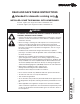
READ AND SAVE THESE INSTRUCTIONS ! Intended for domestic cooking only ! INSTALLER: LEAVE THIS MANUAL WITH HOMEOWNER. In U.S.A., register your range hood online at www.broan.com. In Canada, register your range hood online at www.broan.ca. ! WARNING TO REDUCE THE RISK OF FIRE, ELECTRIC SHOCK, OR INJURY TO PERSONS, OBSERVE THE FOLLOWING: • Use this unit only in the manner intended by the manufacturer. If you have questions, contact the manufacturer at the address or telephone number listed in the warranty.
! WARNING TO REDUCE THE RISK OF A RANGE TOP GREASE FIRE: a) Never leave surface units unattended at high settings. Boilovers cause smoking and greasy spillovers that may ignite. Heat oils slowly on low or medium settings. b) Always turn hood ON when cooking at high heat or when flambeing food (i.e.: Crêpes Suzette, Cherries Jubilee, Peppercorn Beef Flambé). c) Clean ventilating fan frequently. Grease should not be allowed to accumulate on fan, filters or in exhaust ducts. d) Use proper pan size.
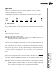
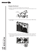
Operation Always turn your hood on before you begin cooking to establish an air flow in the kitchen. Let the blower run for a few minutes to clear the air after you turn off the range. This will help keep the whole kitchen cleaner and fresher. This hood is equipped with infrared sensing controls. To activate it, simply touch the sensor corresponding to the desired function and/or intensity. At the touch of the sensor, a beep is emitted to acknowledge the command.
LIGHTING/LIGHT INTENSITY CHANGE To turn the lighting ON, touch the sensor corresponding to the desired lighting intensity and the sensor will illuminate. When the lighting is ON, touch the sensor corresponding to the active light intensity to turn the lighting OFF and memorize the intensity.
Cleaning and Maintenance Proper maintenance of the Range Hood will assure proper performance of the unit. MOTORS The motors are permanently lubricated and never need oiling. If the motor bearings make excessive or unusual noise, replace the motor with the exact service motor. The fan wheel should also be replaced. GREASE FILTERS The grease filters should be cleaned frequently. Use a warm dishwashing detergent solution. Grease filters are diswasher safe.
For ADA compliance installation guidelines, please visit www.broan.com Recommended Tools and Accessories for Installation • • • • • • • • • • • • • • • Measuring tape Phillips screwdriver no.
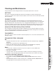
Contents Before proceeding to the installation, check the contents of the box. If items are missing or damaged, contact the manufacturer. Make sure that the following items are included: * FIND INSIDE ONE PACKAGING STYROFOAM OF HOOD (1) 7” ROUND DUCT CONNECTOR (1) 3¼” X 10” DAMPER ASSEMBLY* (2) GREASE FILTERS EZ1 COMPONENTS Use this template for marking; do not attempt to cut out the ducting hole through it. NOTE: These cutouts are clearance holes; they do not need to be the exact size of ducting.
Prepare the Hood 1 ] If present, remove all protective polyfilm from the hood and/or parts. 2 ] Remove 7” Round Duct Plate from top/back of hood (see illustration below). Keep the screws for further use. 7” ROUND DUCT PLATE 2 SCREWS 3 ] Using the finger cup, remove the grease filters from the hood by pushing down and tilting filters out .
5 ] Remove the parts bag, taped on the inner back of hood, near the left corner. Remove the EZ1 brackets from inside the hood by cutting off the tie wrap. Discard the tie wrap. EZ1 BRACKETS PARTS BAG LOCATION 6 ] Remove Electrical Power Cable Knockout from top (vertical exhaust) or back (horizontal exhaust) of hood. For knockout removed from back of hood, install an appropriate strain relief, 1/2” diameter (not included). For knockout removed from top of hood, the strain relief will be installed later.
DUCTED INSTALLATION ONLY 8 ] Remove 3¼” x 10” vertical, 3¼” x 10” horizontal (both are the rectangular central knockout plates, see hatched areas) or 7-inch round knockout plate as appropriate for your ducting method (see FIGURES 1 A and 1 B).
Prepare the Hood Location NOTE: Before starting installation, read all the steps of these instructions. Use the illustration below to identify your kitchen cabinet type. FRAMED CABINET FRAMELESS CABINET This manual covers 2 kinds of installation: the standard (without EZ1 brackets) and the EZ1 one-person installation system (using included template and brackets). For the standard installation, go to page 18.
4 ] Drill a 1/8” dia. pilot hole for house wiring, at B location on template. 5 ] Use a sharp pencil or 1/8” drill bit to mark the locations for the appropriate duct access holes (16 locations for 7” round duct, or 4 corner locations for rectangular duct). Remove the template. 6 ] Draw the border for the exhaust ducting by linking its marks (16 for round duct and 4 for rectangular duct), then cut the opening in the cabinet bottom (vertical exhaust) or in the wall (horizontal exhaust).
FRAMELESS CABINET Refer to the marking on brackets to determine the correct installation side and orientation. X Y Z 3X [ \ 7/64” against the wall. Draw a line on the outer edge of the bracket (as shown). marked line, keeping the rear end edge leaning on the wall. Use a pencil to mark 3 holes. Remove the bracket. Using a 7/64” drill bit, drill 3 holes where marked. Assemble the bracket to the cabinet bottom using a Phillips screwdriver and 3 provided countersunk wood screws.
Install the Hood (EZ1 Bracket) NOTE: The following procedure applies to both frame or frameless cabinet installations. 1 ] Run house power cable between service panel and hood location. 2 ] There are 2 pairs of recessed holes on each side of the top of the hood (on rear: A and B, on front C and D on illustration below); these holes allow the range hood to hang on the brackets (previously installed).
7 ] For framed cabinet, secure the hood to the EZ1 brackets using four (4) no. 8-18 x 1/2” metal screws (included in parts bag). Insert two (2) screws per side, in the slots (as shown in insets on illustration below). 8 ] For frameless cabinet, secure the hood to the cabinet using four (4) no. 8 x 5/8” round head wood screws (included in parts bag). Insert two (2) screws per side, in the slots (as shown in insets on illustration below).
Standard Installation (without EZ1 brackets) 1 ] Use the proper diagram below for placement of ductwork and electrical cutout in cabinet or wall. For a non-ducted installation, DO NOT cut a duct access hole, only cut the hole for electrical wiring.
Install the Hood (Standard Installation) NOTE: Two installers are recommended because of the weight of this hood. 1 ] Run house power cable between service panel and hood location. For hood with power cable access located on back of hood, run the house power cable into the hood through the strain relief previously installed in step 6 on page 11. For hood with power cable access located on top, tighten the strain relief to the power cable before inserting the strain relief in the knockout hole.
Connect the Wiring ! WARNING Risk of electric shock. Electrical wiring must be done by qualified personnel in accordance with all applicable codes and standards. Before connecting wires, switch power off at service panel and lock service disconnecting means to prevent power from being switched on accidentally. MOTORS GROUND WIRE GROUND SCREW HOUSE POWER CABLE 1 ] Connect House Power Cable to range hood wiring: BLACK to BLACK, WHITE to WHITE and GREEN or bare wire under GREEN ground screw.
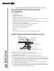
G/Y Ground INSTALLATION MANUAL J2 7 4 5 6 1 2 3 J1 4 5 1 2 3 WIRING DIAGRAM W BK 10 8 6 4 2 J7 9 7 5 3 1 J6 1 2 3 4 5 6 ADA RF ADA Override User Interface Control Board J4 Line Neutral Note: The control board is viewed with the connectors on the opposite side of the board.
ALT3 SERIES C B N D L E M K F J G H I KEY NO. PART NO.
INSTALLATION MANUAL WARRANTY Limited Warranty Warranty Period and Exclusions: Broan-NuTone LLC and Venmar Ventilation ULC (either being the “Company”) warrants to the original consumer purchaser of its product (“you”) that the product (the “Product”) will be free from material defects in the Product orits workmanship for a period of one (1) year from the date of original purchase (or such longer period as may be required by applicable law).
WWW.BROAN.COM WWW.BROAN.
Seguridad . . . . . . . . . . . . . . . . . . . . . . . . . . . . . . 3-4 Funcionamiento . . . . . . . . . . . . . . . . . . . . . . . . . 5-6 Limpieza y mantenimiento . . . . . . . . . . . . . . . . . 7 Motores Filtros de grasa Filtros de recirculación Ruedas del ventiladores Limpieza del acero inoxidable Instalación . . . . . . . . . . . . . . . . . . . . . . . . . . . . 8-20 Herramientas y accesorios recomendados para la instalación . . . . . . . . . . . . . . . . . . . . . . .
LEA ESTAS INSTRUCCIONNES Y GUÁRDELAS ! Exclusivamente para cocinas domésticas ! INSTALADOR: ENTREGUE ESTE MANUAL AL PROPIETARIO. En EE.UU., registre su campana de cocina en línea en www.broan.com. En Canadá, registre su campana de cocina en línea en www.broan.ca. ! ADVERTENCIA PARA REDUCIR EL RIESGO DE INCENDIO, DESCARGA ELÉCTRICA O LESIÓN CORPORAL, RESPETE LAS SIGUIENTES INDICACIONE: • Utilice esta unidad únicamente de la forma en que indica el fabricante.
! ADVERTENCIA PARA REDUCIR EL RIESGO DE QUE ARDA LA GRASA EN LA PARTE SUPERIOR DE LA COCINA: a) b) c) d) No deje nunca recipientes de cocina a fuego vivo sin vigilancia. Los desbordamientos producen humo y derrames grasientos que pueden inflamarse. Caliente el aceite despacio, a fuego lento o mediano. Ponga en marcha siempre la campana extractora al cocinar a temperaturas elevadas o al cocinar alimentos flameados (crepas Suzette, cerezas jubilee, res con pimienta flambeada).
Funcionamiento Ponga la campana en marcha siempre antes de empezar a cocinar para crear una corriente de aire en la cocina. Deje funcionar el ventilador impelente varios minutos para limpiar el aire cuando ya haya apagado la cocina. De este modo, la cocina estará más limpia y despejada. Esta campana viene equipada con sensores táctiles infrarrojos. Para activarla, basta con tocar el botón que corresponde a la función y/o intensidad deseada. Al tocar el sensor, un pitido es emitido para confirmar la orden.
ENCENDIDO/AJUSTE DE LA INTENSIDAD DE LAS LUCES Para ENCENDER las luces, toque el sensor correspondiente a la intensidad deseada y el sensor se iluminará. Cuando las luces están ENCENDIDAS, toque el sensor correspondiente a la intensidad actual para APAGAR las luces y memorizar la intensidad. Los módulos LED incluidos con esta campana extractora constituyen la más avanzada tecnología de iluminación LED de superficies de cocción.
Limpieza y mantenimiento El mantenimiento adecuado de la campana permitirá que funcione correctamente. MOTORES Los motores estan lubricados permanentemente y no necesitan engrase nunca. Si los rodamientos de uno motor hacen un ruido excesivo o no habitual, sustituya este motor por otro idéntico. También se debería sustituir su hélice. FILTROS DE GRASA Los filtros de grasa deberían limpiarse con frecuencia. Use una disolución de agua tibia y detergente para vajilla.
Para las directrices de instalación conforme a la ADA, visite www.broan.com Herramientas y accesorios recomendados para la instalación • • • • • • • • • • • • • • • Cinta métrica Destornillador Phillips n.
Contenido Antes empezar la instalación, verifique el contenido de la caja. Si faltan elementos o hay elementos dañados, póngase en contacto con el fabricante. Compruebe que estén en la caja los siguientes elementos: * SE ENCUENTRA EN EL EMBALAJE DE POLIESTIRENO 1) CONECTOR (1) CONJUNTO DE LA DE CONDUCTO CLAPETA DE RETENCIÓN* (2) FILTROS DE GRASA REDONDO DE 3¼” X 10” COMPONENTES EZ1 DE Use this template for marking; do not attempt to cut out the ducting hole through it.
Prepare la campana 1 ] De haberla, retire de la campana y de todas las piezas la película protectora. 2 ] Retire la placa para conducto redondo de 7” de la parte superior trasera de la campana y conserve los tornillos para usarlos posteriormente (véase la ilustración de abajo). PLACA PARA CONDUCTO REDONDO DE 7” 2 TORNILLOS 3 ] Use el orificio de agarre para retirar de la campana los filtros de grasa empujando hacia abajo e inclinando los filtros hacia fuera .
5 ] Retire la bolsa de pieza que esta sujeta con cinta adhesiva a la campana; en la esquina inferior izquierda de la campana. Retire los soportes EZ1 del interior de la campana cortando la tira de amarre, y quite esta tira de amarre. UBICACIÓN DE LA BOLSA DE PIEZAS SOPORTES EZ1 6 ] Retire la parte punzonada para el cable de alimentación eléctrica desde la parte superior (salida vertical) o desde la parte trasera (salida horizontal) de la campana.
INSTALACIÓN CON CONDUCTOS ÚNICAMENTE 8 ] Retire la placa punzonada vertical de 3¼” x 10”, horizontal de 3¼” x 10” (ambos están las placas punzonadas rectangular centrales, veanse las zonas rayadas) o la placa punzonada redonda de 7 pulgadas, según el modo de evacuación elegido (véanse las Figuras 1 A y 1 B).
Prepare la ubicación de la campana NOTA: antes de empezar la instalación, lea todas las etapas de estas instrucciones. Use la ilustración de abajo para reconocer su tipo de armario de cocina. ARMARIO CON ARMAZÓN ARMARIO SIN ARMAZÓN Este manual cubre 2 tipos de instalación: la normal (sin soportes EZ1) y la instalación EZ1 por una persona (usando la plantilla y los soporte provistos). Para la instalación normal, vaya a la página 18.
4 ] Taladre un orificio piloto de 1/8” de diámetro para el cableado de la vivienda, en el punto B de la plantilla. 5 ] Use un lápiz afilado o una broca de 1/8” para marcar los puntos para los orificios de acceso de los conductos (16 puntos para un conducto redondo de 7”, o 4 puntos en las esquinas para un conducto rectangular). Retire la plantilla.
ARMARIO SIN ARMAZÓN Consulte las marcas de los soporte para establecer el lado y la orientación correctos de la instalación (marcas en inglés solamente: front = parte delantera, left = izquierda, lean on rear wall = apoyar contra la pared trasera). X Y Z 3X [ \ 7/64” Alinee el soporte correspondiente al lado del armario, colocando al mismo tiempo la línea marcada manteniendo el borde del extremo trasero apoyado en la pared. Use un lápiz para marcar 3 orificios. Retire el soporte.
Instale la campana (Soporte EZ1) NOTA: El procedimiento siguiente se aplica a las instalaciones en armarios con armazón y sin armazón. 1 ] Lleve el cable de alimentación de la vivienda del tablero de servicio al lugar de la campana. 2 ] Hay 2 pares de orificios rebajados en cada lado de la parte superior de la campana (en la parte trasera: A y B, en la parte delantera C y D en la ilustración de abajo); estos orificios permiten colgar la campana a los soportes (instalados previamente).
7 ] En los armarios con armazón, sujete la campana a los soportes EZ1 por medio de los (4) tornillos para metal no 8-18 x 1/2” (los tornillos vienen en la bolsa de piezas). Introduzca (2) tornillos en cada lado, en las ranuras (como se ve en los detalles de la ilustración de abajo). 8 ] En los armarios sin armazón, sujete la campana al armario por medio de los (4) tornillos de cabeza redonda para madera no 8 x 5/8” (los tornillos vienen en la bolsa de piezas).
Instalación normal (sin soportes EZ1) 1 ] Use el diagrama adecuado de abajo para colocar los conductos y la alimentación eléctrica en el armario o en la pared. Para una instalación sin conductos, NO corte el orificio de acceso al conducto; corte sólo el orificio para el cableado eléctrico.
Instale la campana (Instalación normal) NOTA: Debido al peso de esta campana, se aconseja que la instalen dos instaladores. 1 ] Lleve el cable de alimentación de la vivienda del tablero de servicio al lugar de la campana. Si el orificio de acceso del cable alimentación de la campana este en su parte trasera, lleve el cable de alimentación de la vivienda a la campana a través de la descarga de presión instalada previamente en la etapa 6 en la página 11.
Conecte el cableado ! ADVERTENCIA Riesgo de descarga eléctrica. El cableado eléctrico debe hacerlo personal cualificado de acuerdo con los códigos y normas aplicables. Antes de conectar los hilos, corte la corriente en el tablero de servicio y bloquee éste para evitar que se ponga en marcha accidentalmente.
4 6 8 10 3 5 7 9 7 4 5 6 1 2 3 J1 4 5 1 2 3 J7 2 1 J6 1 2 3 4 5 6 ADA RF Interruptor de anulación ADA Transformador Interfaz del usuario V/AM B NE MANUAL DE INSTALACIÓN AZ AZ R R 1 12 CN3 3 42 Interfaz del usuario Manga termo-retráctil Transformador 24 V Clase 2 NE R (L) NA (M) NE (H) B NE R G G G B R NE NE R DIAGRAMA DE CABLEADO Tierra Neutro J4 Placa electrónica J2 4 Línea Nota: La placa electrónica es vista con los conectadores en el lado opuesto de la placa electrón
SERIE ALT3 C B N D E L M K F J G H MANUAL DE INSTALACIÓN PIEZAS DE REPUESTO I 22 CANTIDAD ACERO N.o N.o DE PIEZA DESCRIPCIÓN INOX. 30" 36" 1 S97020031 PLACA DE CUBIERTA DE RECIRCULACIÓN, ACERO INOX. (INCLUYE TORNILLOS) 1 1 2 SR680508 PLACA DE CONDUCTO REDONDO DE 7” (INCLUYE TORNILLOS) 1 1 3 S97020534 CONJUNTO DE CLAPETA DE 3¼” X 10” (INCLUYE TORNILLOS) 1 1 4 S97020412 CONDENSADOR (INCLUYE TIRA DE AMARRE) 2 2 5 S97021326 MONTAJE DEL VENTILADOR ROTACIÓN A DERECHA (INCLUYE N.° 4, N.
MANUAL DE INSTALACIÓN GARANTÍA Garantía limitada Periodo y exclusiones de la garantía: Broan-NuTone LLC o Venmar Ventilation ULC (sea esta la “Compañía”) garantiza al consumidor comprador original de su producto (“usted”) que el producto (el “Producto”) estará libre de defectos en materiales o en mano de obra, por un periodo de un (1) año a partir de la fecha de compra original (o por un periodo mayor según sea requerido por la legislación aplicable).