User Guide
Manuals
Brands
BroadLink Manuals
PCB Antenna
BroadLink BL3372-P_1V1 PCB Antenna
1
2
3
4
5
6
7
8
9
10
Table Of Contents
1. Overview
2. Basic Specifications
2.1. Power Consumption
2.2. Working Environment
3.Radio Specifications
3.1. Basic Radio Specification
3.2. Radio Performance
3.2.1 IEEE802.11b
3.2.2. IEEE 802.11g
3.2.3IEEE802.11n
4. BL3372-P_1V1 Hardware Information
4.1. PIN Sequence
4.2. PIN Definitions
4.3 Recommendations
4.4. Mechanical Dimensions
4.5. Recommended Pad Size
4.6. Certifications
4.7. Label
4.7. Shielding Case Dimensions
4.8. Packaging
5. Reference Design
5.1. UART Interface Design
5.2. Power Supply Requirement
Revision History
Copyrights
B
r
o
a
d
L
i
n
k
-
10
-
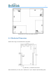
Fig
2
BL3372-P_1V1
Recommended
PCB
layout
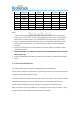
4.4.
Mechanical
Dim
ensions
Please
refer
to
Fig
3
for
th
e
dimensions
of
modu
le.
Fig
3
BL3372-P_1V1
Module
Dimensions
Note:
Dime
nsions
(17.7
±0.2)
mm
*
(30
±0.2)
mm
*
(3.6
±
10%)mm
(with
shielding
case)
1
...
...
8
9
10
11
12
...
...
20