
User guide


6
Avago Technologies Motion Control Encoders in Electrical Motor Systems: Design Guide
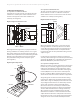
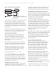
1 Cycle
Window
Rop= Optical Radius
Rop
Bar
For rotary encoder applications, the resolution is most
commonly dened by the CPR of the encoder. Due to the
quadrature relationship of an incremental output, the
nal resolution of the encoders can be quadrupled by
decoding each rising and falling edge of the two channel
encoder signals.
For example, a 1000 CPR encoder can provide an eective
4000 quadrature counts after the 4X decode at the
customer interface.
3.2 Operating Temperature
Operating temperature denes the working range that
an encoder is designed for. Within the temperature range,
the encoder is expected to perform as specied in the
datasheet performance reliably.
Encoders are designed with components and materials
that can withstand the temperature range specied.
Rigorous tests and qualication is carried out to ensure
a product’s quality and reliability.
Operating temperatures are important to encoder
applications, as the environment the encoder is working in
varies from one application to another. For encoders meant
for direct integration into a motor, the motor coil can be
close to the encoder and temperatures of up to 100°C or
higher may be expected.
3.3 Output Signals
Digital signal is commonly used due to its direct interface
with modern control electronics. Analog signals provide
exibility with potentially very high feedback rate to system
designers. A single channel encoder only provides positional
and speed info but cannot dierentiate the direction of
motion. A 2-channel encoder provides the directional
information. A 3-channel encoder (with index) provides
absolute information, typically once per revolution.
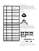
CH. A
CH. B
CCW Rotation CW Rotation
360°e
90°e
For an incremental encoder, the 2-channel output signals
are in quadrature, i.e. the two periodical signals are
identical but oset by 90°e. The quadrature signals provide
the information on direction of rotation. In one direction,
Channel A leads Channel B. In the counter direction
Channel B leads Channel A.
The incremental encoder is typically decoded to provide
counts information, and a decoder and counter are
required. The decoding and count functions can be easily
implemented by a microcontroller or accepted directly by
most motor controllers.
The quadrature incremental signals are typically decoded
to obtain up to four times the base CPR. Quadrature
decoding counts both the rising and falling edges of
Channel A and B.
A
x1 x2
Amplitude
Position
x4
B
Count
The absolute encoder does not require a counter or
decoder. The positional information is provided directly.
The absolute encoder signal is output as a serial output.
3.4 Shaft Sizes
Shaft size refers to the motor shaft diameter that the
encoder is mounted to. Shaft sizes are important, as the
diameter will inuence how big or small the shaft is that
it can be tted to. Typically a large motor will also have a
larger shaft size, and vice versa. A small diameter encoder
will only cater to a limited range of shaft sizes in order to
maintain the overall diameter.
3.5 Motor Speed
Motor speed is often referred to as the RPM or revolutions
per minute. The RPM rating denes the typical and
maximum speed that a motor is designed to spin, with
or without load.