Motion Control Encoders in Electrical Motor Systems Design Guide Your Imagination, Our Innovation Sense • Illuminate • Connect
Avago Technologies Motion Control Encoders in Electrical Motor Systems: Design Guide Contents Motion Control Encoders in Electrical Motor Systems 1.0 Introduction 2.0 What are motion control encoders? 2.1 Type of encoders available at Avago Technologies 2.2 Basic Encoder Operations 2.3 Units of measure 3.0 Main Characteristics 3.1 Resolutions 3.2 Operating Temperature 3.3 Output Signals 3.4 Shaft Sizes 3.5 Motor Speed 3.6 Motor Diameter 4.
Motion Control Encoders in Electrical Motor Systems Design Guide 1.0 Introduction As the market becomes increasingly driven by consumer demands, businesses are forced into an intensified effort of meeting those demands to ensure their survival. It is a freefor-all in a business landscape that is filled with unpredictable sentiment and unforgiving circumstances.
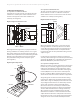
Avago Technologies Motion Control Encoders in Electrical Motor Systems: Design Guide 2.2 Basic Encoder Operations 2.2.2 Operations of a Reflective Encoder 2.2.1 Operations of a Transmissive Encoder A transmissive encoder consists of an emitter, detector, codewheel or codestrip. The emitter and detector are located on the opposite sides of the codewheel or codestrip. (See Diagram 1) The basic elements of reflective encoders are similar to the transmissive encoder.
3.0 Main Characteristics 2.3 Units of measure CPR Cycles per Revolution Defines the number of electrical cycles that an encoder provides in a single revolution. CPR = 2π x LPmm x Rop LPI Lines per Inch Defines the number of window-bar pairs in a length of 1inch Lines per mm Defines the number of window-bar pairs in a length of 1mm. Note that LPmm=LPI/25.
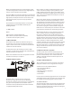
Avago Technologies Motion Control Encoders in Electrical Motor Systems: Design Guide Window Bar Rop= Optical Radius information. A 3-channel encoder (with index) provides absolute information, typically once per revolution. 360°e 1 Cycle Rop CH. A 90°e CH. B CCW Rotation For example, a 1000 CPR encoder can provide an effective 4000 quadrature counts after the 4X decode at the customer interface. 3.2 Operating Temperature Operating temperature defines the working range that an encoder is designed for.
Motor speed will determine the encoder frequency that is needed. A high CPR encoder will need a high frequency rating in order to maintain the same RPM. The motor RPM is increasingly important in providing high dynamic and fast response to various applications, such as high speed pick and place machines. An encoder needs to have the frequency response to keep up with the motor RPM.
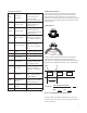
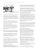
Avago Technologies Motion Control Encoders in Electrical Motor Systems: Design Guide Diagram 4. Brushless DC Motor System with Encoder DC Power Input Driver Power Stage Motor Control Unit Current Sensor Feedback Avago’s Motion Feedback Solution Motor Incremental Encoder, Incremental Encoder with UVW Commutation, Absolute Encoder The brushless DC motor (BLDC) is a synchronous electrical motor that looks very similar to a DC motor.
passes through the slots on the moving tracks, it creates shadows at intervals. Where a shadow is detected, a low state (0) is created. When the light successfully penetrates the slot a high state (1) is created. The position of the shaft is detected by reading the pattern of 1’s and 0’s. For higher resolution single-turn encoders, incremental tracks are added. These tracks enable the interpolation of signals.
Avago Technologies Motion Control Encoders in Electrical Motor Systems: Design Guide Avago’s multi-turn absolute encoders are recognized for their reliability and consistency in providing highly accurate absolute information for multiple revolutions. These encoders have a true mechanical system which eliminates the need of a battery back-up in the event of power failures or sudden stoppage. The absolute multi-turn encoders come in a choice of 12 and 14-bits for applications in a wide range of industries.
5.2 Selection Table: Encoders by Operating Temperature Max RPM Resolution No.
Avago Technologies Motion Control Encoders in Electrical Motor Systems: Design Guide 5.3 Encoders for BLDC Motor System: By Output Signal Applications are generally designed to receive and transmit three different forms of output signal: analog, digital or synchronous serial interface (SSI). Analog output signals appear as a quasi-sinusoidal wave (unprocessed) while digital output signals resemble square waves (processed). 5.3.
a 5 volt supply. Line drivers are low output impedance devices, designed to drive signals over longer distances, and are normally used with a matched receiver. 5.3.2 Analog signal output incremental encoders Encoders that provide analog output are typically required by high-end motors such as the high resolution servo motors. Analog signal output encoders have the ability to achieve higher resolution through external interpolation electronics. 5.3.
Avago Technologies Motion Control Encoders in Electrical Motor Systems: Design Guide dependent of the motor selected for the particular application. Avago Technologies offers encoder systems which match a wide range of motor shaft sizes. 5.4.1 Large shaft size Encoders in the large shaft size category are suitable for shaft sizes from 10mm or above, depending on the type of encoder selected. Some of the encoders listed here can easily fit larger shaft sizes through the use of a larger OD codewheel. 5.4.
5.6 Encoders for BLDC Motor System: By Motor Diameter Electrical motors are used in a diverse range of applications stretching from industrial usage, medical equipments office automation to consumer products. Taking this into consideration, the motor system itself is offered in a variety of sizes depending on the usage, capacity , etc. Here, Avago’s encoders are developed to meet different motor diameter sizes. The encoders are suitable for motors that measure from 10mm to 56mm in diameter, or larger. 6.
Your Imagination. Our Innovation From the smartphone that keeps you in touch, to the fiber optic network that keeps a $10-billion corporation connected, we get our information these days through an ever-increasing array of sophisticated device technologies. And behind it all, are semiconductors that sense, illuminate, and connect the signals in order to process that digital data.