
Datasheet


Description
The Proximity sensor has several possible applications for
multimedia product, Automation, and Personal handled.
The proximity sensor is basically made up of the emitter
(infrared LED) and detector (photodiode). The block
diagram of the sensor is shown in Figure 13. The emitter
will emit IR light pulse. This light travels out in the eld
of view and will either hit an object or continue. No light
will be reected when no object is detected. On the other
hand, the detector will detect the reected IR light when
it hits the object.
Figure 13. Proximity sensor block diagram
(refer to Pins Conguration Table)
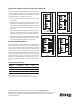
Interface to the Recommended I/O chip
The HSDL-9100 is general interface with the GPIO pin of
the controller chipset. The LED_A, pin1 is connected to
the PWM port alternatively the external timer circuitry
can be used to drive the LED. The DET_K, pin 4 is interface
to the signal conditioning before driving the GPIO port.
Figure 14 shows the hardware reference design with
HSDL-9100.
* The LED can be driven by the PWM output or the external timer circuitry.
Figure 14. Mobile Application Platform
Appendix B: General Application Guide for the HSDL-9100
STN/TFT LCD Panel
Logic Bus DriverMemory Expansion
Power Management
Touch Panel
PCM Sound
Audio Input
Key Pad
Antenna
Mobile Application
chipset
IR Transceiver
ROM
FLASH
SDRAM
LCD Control
A/D
Memory I/F
Baseband
controller
Peripherial
interface
AC97
sound
I2S
IrDA
interface
Signal Conditional
*IR LED driver
GPIO
PWM
HSDL-9100
Photodiode
LED
Photodiode
cathode
LED
anode
Photodiode
anode
LED
cathode
4
1
3
2