
Datasheet


12
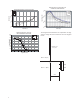
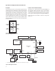
Figure 15. HSDL9100 configuration with controller chipset
The next section discusses interfacing configuration with
general processor including the recommended signal
conditional circuitry.
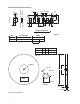
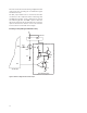
The DET_A pin of HSDL-9100 is connected to the filter
circuit then to the comparator before interfacing with
the GPIO pin. The filter circuit is implement to provide
the ambient light filter. The PWM is pulse to drive the
LED_K pin alternative the external timer 555 can also be
replaced. The detector distance can be varies with the
increase/decrease of the LED current supply.
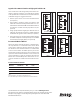
Interfacing circuitry with signal conditional circuitry
10 Ω
GND
PWM
220 Ω
BC848
LEDK
LEDA
VCC
DETK
DETA
GND GND
BC846B
1 MΩ
VCC
VCC
24 KΩ
36 KΩ
22 KΩ
220 pf
VCC
47 kΩ
300 Ω
GND
Signal conditioning circuitry
GPIO
HSDL-9100
controller chipset