
Datasheet


8
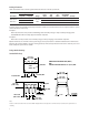
Parameter Symbol Min. Typ. Max. Unit Test Condition Fig. Note
Input-Output
Momentary Withstand
Voltage
V
ISO
3750 Vrms RH < 50%,
t = 1 min.
T
A
= 25°C
16,17
Resistance
(Input-Output)
R
I-O
>10
9
Ω V
I-O
= 500 V
DC
18
Capacitance
(Input-Output)
C
I-O
1.2 pF ƒ = 1 MHz 18
Package Characteristics
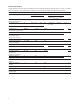
AC Electrical Specications
Unless otherwise noted, all typicals and gures are at the nominal operating conditions of V
IN+
= 0, V
IN-
= 0 V, V
DD1
=
V
DD2
= 5 V and T
A
= 25°C; all Min./Max. specications are within the Recommended Operating Conditions.
Parameter Symbol Min. Typ. Max. Unit Test Conditions Fig. Note
V
OUT
Bandwidth
(-3 dB) sine wave.
BW 50 100 kHz V
IN+
= 200 mV
pk-pk
12,13
V
OUT
Noise N
OUT
31.5 mVrms V
IN+
= 0.0 V 13
V
IN
to V
OUT
Signal Delay
(50 – 10%)
t
PD10
2.03 3.3 µs V
IN+
= 0 mV to 150 mV
step.
Measured at output of
MC34081 on Figure 15.
14,15
V
IN
to V
OUT
Signal Delay
(50 – 50%)
t
PD50
3.47 5.6
V
IN
to V
OUT
Signal Delay
(50 – 90%)
t
PD90
4.99 9.9
V
OUT
Rise/ Fall Time
(10 – 90%)
t
R/F
2.96 6.6
Common Mode
Transient
Immunity
CMTI 10.0 15.0 kV/µs V
CM
= 1 kV, T
A
= 25°C 16 14
Power Supply
Rejection
PSR 170 mVrms With recommended
application circuit.
15