
Datasheet


17
1. THE BASICS
1.1: Why should I use the HCPL-7800(A) for sensing cur-
rent when Hall-eect sensors are available which don’t
need an isolated supply voltage?
Available in an auto-insertable, 8-pin DIP package, the
HCPL-7800(A) is smaller than and has better linearity,
oset vs. temperature and Common Mode Rejection
(CMR) performance than most Hall-eect sensors. Ad-
ditionally, often the required input-side power supply
can be derived from the same supply that powers the
gate-drive optocoupler.
2. SENSE RESISTOR AND INPUT FILTER
2.1: Where do I get 10 mΩ resistors? I have never seen one
that low.
Although less common than values above 10 Ω, there
are quite a few manufacturers of resistors suitable for
measuring currents up to 50 A when combined with
the HCPL-7800(A). Example product information may be
found at Dale’s web site (http://www.vishay.com/vishay/
dale) and Isotek’s web site (http://www.isotekcorp.com).
2.2: Should I connect both inputs across the sense resistor
instead of grounding V
IN-
directly to pin 4?
This is not necessary, but it will work. If you do, be sure
to use an RC lter on both pin 2 (V
IN+
) and pin 3 (V
IN-
) to
limit the input voltage at both pads.
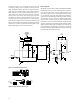
2.3: Do I really need an RC lter on the input? What is it
for? Are other values of R and C okay?
The input anti-aliasing lter (R=39 Ω, C=0.01 µF) shown
in the typical application circuit is recommended for
ltering fast switching voltage transients from the input
signal. (This helps to attenuate higher signal frequencies
which could otherwise alias with the input sampling rate
and cause higher input oset voltage.)
Some issues to keep in mind using dierent lter resistors
or capacitors are:
1. Filter resistor: Input bias current for pins 2 and 3: This
is on the order of 500 nA. If you are using a single
lter resistor in series with pin 2 but not pin 3 the IxR
drop across this resistor will add to the oset error of
the device. As long as this IR drop is small compared
to the input oset voltage there should not be a
problem. If larger-valued resistors are used in series,
it is better to put half of the resistance in series with
pin 2 and half the resistance in series with pin 3. In
this case, the oset voltage is due mainly to resistor
mismatch (typically less than 1% of the resistance
design value) multiplied by the input bias.
FREQUENTLY ASKED QUESTIONS ABOUT
THE HCPL-7800(A)
2. Filter resistor: The equivalent input resistance for
HCPL-7800(A) is around 500 kΩ. It is therefore best
to ensure that the lter resistance is not a signicant
percentage of this value; otherwise the oset voltage
will be increased through the resistor divider eect.
[As an example, if R
lt
= 5.5 kΩ, then V
OS
= (Vin * 1%)
= 2 mV for a maximum 200 mV input and V
OS
will
vary with respect to Vin.]
3. The input bandwidth is changed as a result of this
dierent R-C lter conguration. In fact this is one
of the main reasons for changing the input-lter R-C
time constant.
4. Filter capacitance: The input capacitance of the
HCPL-7800(A) is approximately 1.5 pF. For proper
operation the switching input-side sampling
capacitors must be charged from a relatively xed
(low impedance) voltage source. Therefore, if a lter
capacitor is used it is best for this capacitor to be a
few orders of magnitude greater than the C
INPUT
(A
value of at least 100 pF works well.)
2.4: How do I ensure that the HCPL-7800(A) is not de-
stroyed as a result of short circuit conditions which cause
voltage drops across the sense resistor that exceed the rat-
ings of the HCPL-7800(A)’s inputs?
Select the sense resistor so that it will have less than 5 V
drop when short circuits occur. The only other require-
ment is to shut down the drive before the sense resistor
is damaged or its solder joints melt. This ensures that the
input of the HCPL-7800(A) can not be damaged by sense
resistors going open-circuit.
3. ISOLATION AND INSULATION
3.1: How many volts will the HCPL-7800(A) withstand?
The momentary (1 minute) withstand voltage is 3750 V
rms per UL 1577 and CSA Component Acceptance Notice
#5.
4. ACCURACY
4.1: Can the signal to noise ratio be improved?
Yes. Some noise energy exists beyond the 100 kHz
bandwidth of the HCPL-7800(A). Additional filtering
using dierent lter R,C values in the post-amplier
application circuit can be used to improve the signal
to noise ratio. For example, by using values of R3 = R4
= 10 kΩ, C5 = C6 = 470 pF in the application circuit
the rms output noise will be cut roughly by a factor of
2. In applications needing only a few kHz bandwidth
even better noise performance can be obtained. The
noise spectral density is roughly 500 nV/š Hz below
20 kHz (input referred).