
Datasheet


13
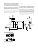
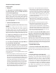
Figure 17. Recommended Supply and Sense Resistor Connections.
HCPL-7800
C1
0.1 µF
R2
39 Ω
GATE DRIVE
CIRCUIT
FLOATING
POWER
SUPPLY
* * *
HV+
* * *
HV-
* * *
-+
R
SENSE
MOTOR
C2
0.01 µF
D1
5.1 V
-
+
R1
Application Information
Power Supplies and Bypassing
The recommended supply con-nections are shown in
Figure 17. A oating power supply (which in many ap-
plications could be the same supply that is used to drive
the high-side power transistor) is regulated to 5 V using
a simple zener diode (D1); the value of resistor R4 should
be chosen to supply sucient current from the existing
oating supply. The voltage from the current sensing
resistor (Rsense) is applied to the input of the HCPL-
7800(A) through an RC anti-aliasing lter (R2 and C2).
Although the application circuit is relatively simple, a few
recommendations should be followed to ensure optimal
performance.
The power supply for the HCPL -7800(A) is most often
obtained from the same supply used to power the
power transistor gate drive circuit. If a dedicated supply
is required, in many cases it is possible to add an ad-
ditional winding on an existing transformer. Otherwise,
some sort of simple isolated supply can be used, such as
a line powered transformer or a high-frequency DC-DC
converter.
An inexpensive 78L05 three-terminal regulator can also
be used to reduce the oating supply voltage to 5 V. To
help attenuate high-frequency power supply noise or
ripple, a resistor or inductor can be used in series with
the input of the regulator to form a low-pass lter with
the regulator’s input bypass capacitor.