
Datasheet


Features
• Performance specied for bommon IPM applications
over industrial temperature range: -40°C to 100°C
• Fast maximum propagation delays
t
PHL
= 480 ns
t
PLH
= 550 ns
• Minimized Pulse Width Distortion
PWD = 450 ns
• 15 kV/µs minimum common mode transient immu-
nity
at V
CM
= 1500 V
• CTR > 44% at I
F
= 10 mA
• Safety approval:
UL Recognized
-3750 V rms / 1 min. for HCPL-4506/0466/J456
-5000 V rms / 1 min. for HCPL-4506 Option 020
and HCNW4506
CSA Approved
IEC/EN/DIN EN 60747-5-2 Approved
-V
IORM
= 560 Vpeak for HCPL-0466 Option 060
-V
IORM
= 630 Vpeak for HCPL-4506 Option 060
-V
IORM
= 891 Vpeak for HCPL-J456
-V
IORM
= 1414 Vpeak for HCNW4506
Applications
• IPM isolation
• Isolated IGBT/MOSFET gate drive
• AC and brushless DC motor drives
• Industrial inverters
CAUTION: It is advised that normal static precautions be taken in handling and assembly
of this component to prevent damage and/or degradation which may be induced by ESD.
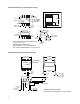
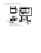
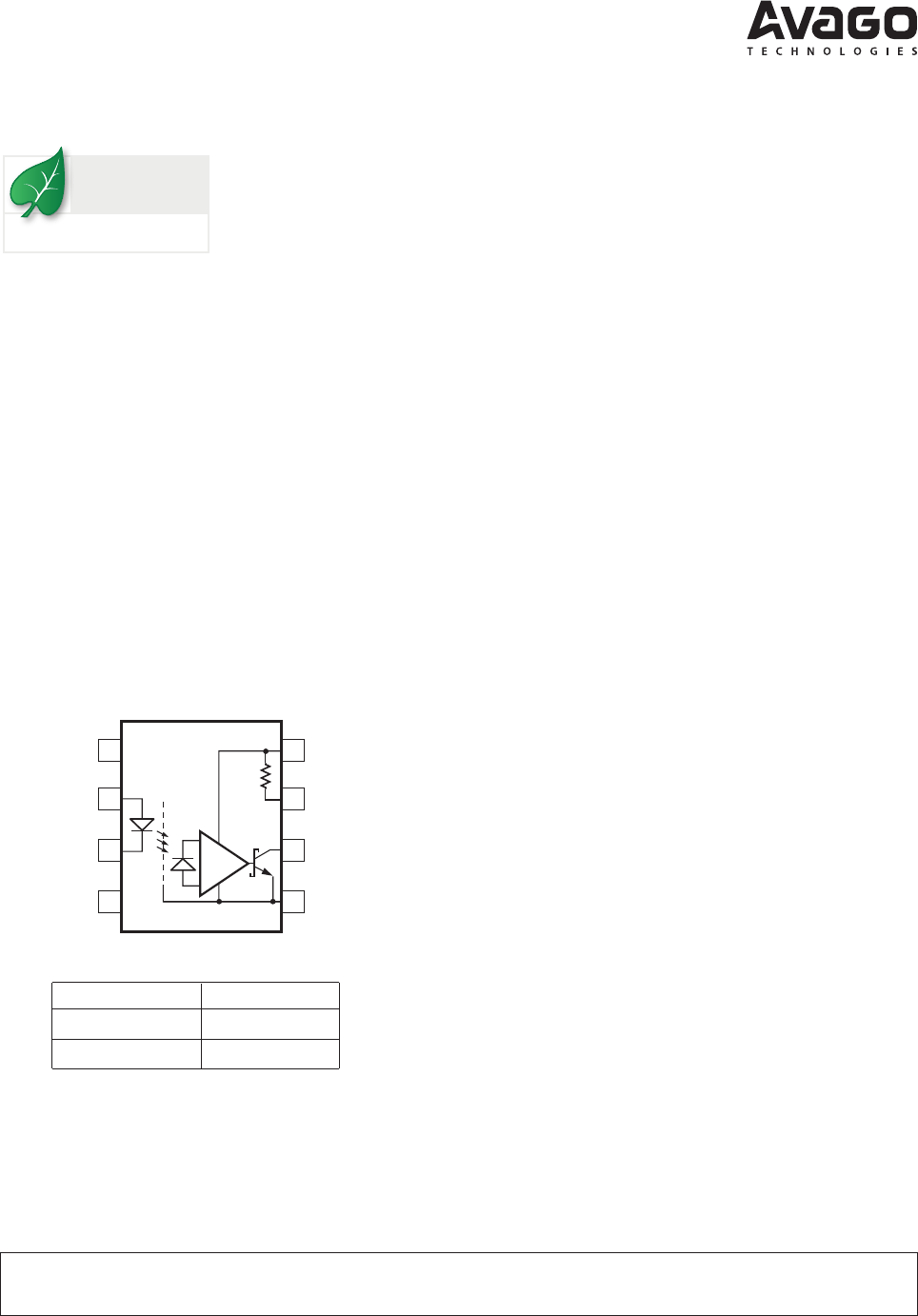
HCPL-4506 Functional Diagram
8
7
6
1
3
SHIELD
5
2
4
20 kΩ
NC
ANODE
CATHODE
NC
V
CC
V
L
V
O
GND
HCPL-4506/J456/0466, HCNW4506
Intelligent Power Module and Gate Drive Interface Optocouplers
Data Sheet
Description
The HCPL-4506 and HCPL-0466 contain a GaAsP LED while
the HCPL-J456 and the HCNW4506 contain an AlGaAs LED.
The LED is optically coupled to an integrated high gain
photo detector. Minimized propagation delay dierence
between devices makes these optocouplers excellent so-
lutions for improving inverter eciency through reduced
switching dead time.
An on chip 20 kΩ output pull-up resistor can be enabled by
shorting output pins 6 and 7, thus eliminating the need for
an external pull-up resistor in common IPM applications.
Specications and performance plots are given for typical
IPM applications.
Functional Diagram
The connection of a 0.1 µF bypass capacitor
between pins 5 and 8 is recommended.
Truth Table
LED V
O
ON L
OFF H
Lead (Pb) Free
RoHS 6 fully
compliant
RoHS 6 fully compliant options available;
-xxxE denotes a lead-free product