
Datasheet


18
Thermal Coecient Data (units in °C/W)
Part Number A
11
, A
22
A
12
, A
21
A
13
, A
31
A
24
, A
42
A
14
, A
41
A
23
, A
32
A
33
, A
44
A
34
, A
43
HCPL-315J 198 64 62 64 83 90 137 69
Note: Maximum junction temperature for above part: 125°C.
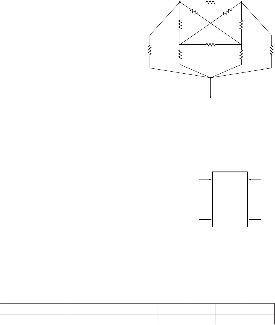
Figure 28b. Thermal Impedance Model for HCPL-315J.
θ
6
θ
5
θ
9
θ
4
θ
8
θ
7
θ
10
θ
1
θ
3
θ
2
LED 1 LED 2
AMBIENT
DETECTOR 1 DETECTOR 2
HCPL-3150 fig 28b
P
E1
HCPL-3150 fig 28b
P
E2
P
D1
P
D2
Thermal Model Dual-Channel (SOIC-16) HCPL-315J Op-
toisolator
Denitions
θ
1
, θ
2
, θ
3
, θ
4
, θ
5
, θ
6
, θ
7
, θ
8
, θ
9
, θ
10
: Thermal impedances be-
tween nodes as shown in Figure 28b. Ambient Tempera-
ture: Measured approximately 1.25 cm above the opto-
coupler with no forced air.
Description
This thermal model assumes that a 16-pin dual-channel
(SOIC-16) optocoupler is soldered into an 8.5 cm x 8.1
cm printed circuit board (PCB). These optocouplers are
hybrid devices with four die: two LEDs and two detec-
tors. The temperature at the LED and the detector of the
optocoupler can be calculated by using the equations
below.
∆T
E1A
= A
11
P
E1
+ A
12
P
E2
+A
13
P
D1
+A
14
P
D2
∆T
E2A
= A
21
P
E1
+ A
22
P
E2
+A
23
P
D1
+A
24
P
D2
∆T
D1A
= A
31
P
E1
+ A
32
P
E2
+A
33
P
D1
+A
34
P
D2
∆T
D2A
= A
41
P
E1
+ A
42
P
E2
+A
43
P
D1
+A
44
P
D2
where:
∆T
E1A
= Temperature dierence between ambient and LED 1
∆T
E2A
= Temperature dierence between ambient and LED 2
∆T
D1A
= Temperature dierence between ambient and detector 1
∆T
D2A
= Temperature dierence between ambient and detector 2
P
E1
= Power dissipation from LED 1;
P
E2
= Power dissipation from LED 2;
P
D1
= Power dissipation from detector 1;
P
D2
= Power dissipation from detector 2
A
xy
thermal coecient (units in °C/W) is a function of thermal imped-
ances θ
1
through θ
10
.